
Installation manual


Front and Rear Panel Descriptions
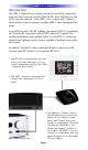
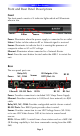
Front
The front panel consists of 4 indicator lights which will illuminate
when in use.
Power: Illuminates when the power supply is connected to an outlet
Status: Flashes in blue when an RF or Network signal is received.
Sensor: Illuminates to indicate that it is sensing the presence of
composite video or AC or DC voltage.
Ethernet: Illuminates when connected to a Network Router
Reset: Press the reset button located under the MRX-1 to restart the
unit.
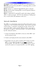
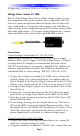
Rear
The rear panel ports are:
Power: Provides connection to included 12V/1Amp Power Supply.
Ethernet: Provides connection to LAN(Local Area network) via RJ45
cable.
Relay NO, NC, COM: Provides configurable switch closure control.
RS-232 Ports: Two RS232 ports provides direct control.
Sensor: Provides connection to one URC Voltage Sensor (VS-1006)
or to one URC Video Sensor (VID-6) for status in sensor based
macros.
IR IN: Allows MRX-1 control from a base station such as a MRF-260
(IR Routing capability is lost from commands coming from the MRF-
260)
MRX-1 BASE STATION
Page 3
Power
Status
Sensor
Ethernet
Ethernet
Power
Relay:NO,
NC, COM
RS-232 Ports
Sensor
IR IN
IR Outputs: #1-6
RFTX Port: #6
RF IN
RF Out
RF ID
Reset: Bottom