
Technical data
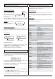
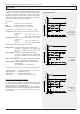

Technical Manual Cold Storage Controllers TKP / TKC x130 - x140Page 14
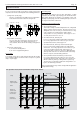
Temperature Alarm
Any over- or undertemperature condition results in
a temperature alarm which causes the normally
energized alarm relay to de-energize. Hereby the
N/O-contacts open and the N/C-contacts close.
To avoid an alarm for short irregular conditions
there is a delay time („
warning delay
“, setpoint
page). The alarm condition is indicated by a LED
at the front of the controller. The alarm is cancelled
automatically if the temperature comes back to
normal. During defrost periods, temperature alarm
will be suppressed. "
remain alm delay
" shows the
remaining time up to an alarm occurs.
Overtemperature Alarm
It is possible to select max. 4 alarm sensors for a
circuit (e.g. 4x "
alarm sensor 1
"). If the temperature
at any of the alarm sensors gets higher than the
effective setpoint plus the „
warning offset
“ setting,
an alarm will be initiated after the delay time.
Undertemperature Alarm
If the temperature at any alarm sensor gets lower
than the „
warn low limit
“ setting, an alarm will come
on with the delay explained above. This setting is
an absolute value and does not refer to the control
setpoint. Undertemperature alarm can be disabled
by "
alm temp low
" (mode page).
Supplementary warning delay during defrost
After a defrost cycle the temperature might take
longer to stabilize and the normal warning delay
turns out to be too short. For this reason the
„
defrost alarm delay
“ (defrost page) setting adds
on to the normal warning delay after defrost.
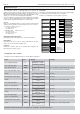
active
p
assive
p
hase
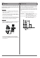
Digital inputs (Optocoupler Inputs)
Switching OFF controller / Cooling Circuits
Sometimes it is necessary to switch off cold
storages completely including the controller, but if
this controller works in a network, the bus-master
detects a malfunction and generates an alarm.
Controller Off
If a digital input is assigned to the function „
Unit
OFF actHigh
“ and is connected to phase, all
control functions are disabled. The display
continues working, but no alarm will be activated.
This is memorized in the list of the 'historical
failures'. „
Unit OFF actLow
“ disables the functions
with 0V at the digital input.
Circuit Off
Each digital input can be configured to switch off
one ore more cooling circuits ("
circuit OFF X
").
When connected to phase, all regulation and
control functions and temperature alarms of the
concerned circuits are disabled. Nevertheless the
others are still working. This is memorized in the
list of the 'historical failures'.
Relay function 'unit on'
The function 'unit on', assigned to an output relay,
has the effect that this relay keeps switched on
during normal operation and keeps switched off
while the controller unit is disabled by digital input
or by interface. So this relay can be used to switch
a function which should be active while the controller
unit does not work.
Security Chain Monitoring
When using the controller for single compressor
applications, one of the digital inputs can be used
for monitoring the security devices ("
security chain"
)
of the compressor. Normally the digital input is
connected to phase. But if the input is open, the
controller waits for the timer „
sec chain delay
“
(setpoint page) then cooling and fan are switched
off, a running defrost period is terminated and a
new defrost start is impossible. The alarm relay will
be activated. Parameter "
rem strt sec ch
" shows
the remaining time up to a controller unit response.
Door Contact
Each control circuit can get a a door contact input.
If the door contact input is connected to phase, the
fan of the circuit stops immediately. If the door is
open > 3 minutes, cooling will stop too. Parameter
"
status
" shows the circuit which is switched off. If
the door is open > 5 minutes, the failure message
"
door X
" will be generated.
Cooling and fan will restart:
- when door is closed or
- when temperature exceeds the warning limits or
- when door opening exceeds the time set by „
door
alm delay
“ (setpoint page). At the same time the
alarm relay will be activated.
Exception:
If no alarm sensor is assigned or if
the temperature is above the alarm
limit „
warning offset
“, then cooling
continues without interruption.
The cooling keeps switched ON and the fan
starts again, so the door opening is ignored.
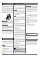
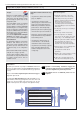
Unit Text
In the mode page you have the possibility to define
a specific text (max. 16 characters) for the controller,
e.g. „apple-store“. This name will be indicated on
the screen of the compound controller VPR 19000
or on a PC with the software
COOLVision
.
Change text:
• select parameter „unit text“ (mode page)
• push „PROG“, the first character position flashes
(eventually, you must enter the access code
before)
• change character by the up/down-keys.
• press „PROG“ to confirm
• the next character flashes
• change this character by the up/down-keys.
....and so on
• press „PROG“ to confirm the last character.
Changing the text can also be made by the software
'COOLVision'.
Display Language
The language used on display can be changed by
"
Sprache/Language
" (mode page) to german,
english, french or dutch.
Real Time Clock
The built-in real time clock is battery buffered,
which works for (typ.) 3 years without mains voltage.
Date and Time can be set on the 'mode page'.
An automatic summer / winter switching (parameter
„
summer/ winter
“) considers the current EU-rules
from 1996 (EU 96), but it can also switched off.
Door Open monitoring
Each time when door is open, the controller adds
this time to the total opening time of that day „
door
open x
“ (actual page). If the total opening time
exceeds the time set by „
door time limit
“ (setpoint
page) then an alarm will be generated. The failure
message will be forwarded at the point in time
determined by „
runtime mess at
“ (mode page) and
is cancelled automatically 1 hour later. "
rem door
open 1
" thru "
rem door open 4
" show the remaining
time up to the alarm message.
Light
One of the relays can execute the function „
light
“,
suitable to control lightings. In this case, the relay
switches together with the night settings „
night
setp. ON
“ and „
night setp. OFF
“ (mode page).
During „day“ the relay is activated.
External Alarm
The digital inputs can execute the job „
alarm input
x
“. While normal operation, the input is connected
to mains phase. When the voltage drops down, a
delay time starts „
OC inp alm delay
“ (setpoint
page). After this timer is run down, a failure message
will be generated.
Forced Refrigeration and Defrost Lock
See chapter 'Adding controller units'.