2200 Corporate Drive Troy, OH 45373 Phone: (937) 440-0100 Fax: (937) 440-0277 WC 1 WELD SEQUENCE CONTROLLER Operation / Installation Manual Manual Part Number: C8M5002 Date: July 9, 2002 Revised: July 24, 2003 July 24, 2003 Manual No.
July 24, 2003 Manual No.
TABLE OF CONTENTS 1.0 1.1 1.2 1.3 1.4 2.0 GENERAL DESCRIPTION ............................................................................................ 1 OVERVIEW ..........................................................................................................................................................1 CONTROL OUTPUTS ...........................................................................................................................................1 CONTROL INPUTS ................
8.2 WC 1 CONTROL ENCLOSURE - CAPSTAN MOTOR DRIVE LAYOUT P/N: C3A5004 .......................................... 23 8.3 OPERATOR PENDANT P/N: C3A5006 ............................................................................................................. 24 9.0 ENCLOSURE PARTS LISTS ...................................................................................... 25 9.1 WC 1 CONTROL ENCLOSURE - STANDARD LAYOUT P/N: C3A5003 ............................................................... 25 9.
1.0 GENERAL DESCRIPTION 1.1 Overview The following is a brief description of the WC 1 Thermal Arc Weld Sequence Controller. The WC 1 controller is based on an embedded micro controller. The Controller provides two 0-10 VDC programmable outputs, one is used to control the Thermal Arc Plasma Power source and the second, controls a Cold Wire Feed Motor Drive Control. The Controller provides 32 user selectable weld schedules. 1.2 Control Outputs The controller has five solid-state isolated relay outputs.
• INP 3 – SCHED 2/ PARAMETER SELECT - User definable spare input. Under Remote Schedule Mode this input can be used for weld schedule selection (Bit 2). Under Remote Control Mode this input is used to select the parameter to Increase/Decrease. When Cleared the Current is selected. When Asserted the Wire Feed speed parameter is selected. This option is only active when the optional wire drive and when the Remote control mode is enabled. • INP 4 – SCHED 3/ INCREASE PARAMETER – User definable spare input.
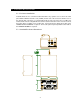
2.0 CONTROL INSTALLATION 2.1 Enclosure Installation Install the Enclosure in a convenient location that allows easy operator access to the front control panel. Allow a minimum clearance of 6” (152mm) from the rear of the enclosure to allow access for the external cable connections. To permanently mount the enclosure remove the four rubber feet and mount the enclosure using blind-hole fasteners located on the bottom of the enclosure. Connect the Power cable to a suitable source of AC power.
2.3 Remote Control Receptacle The optional remote control receptacle provides a basic operational control interface to the WC 1 controller. The following is the pin-out and control function for the 9 pin receptacle. PIN DESCRIPTION 1 +24 vdc @ 100 ma. Power Output 2 ESTOP – 24 VDC input 3 CYCLE START – 24 VDC input 4 INC – 24 VDC Input. Increase the current during the weld cycle 5 DEC – 24 VDC Input.
3.0 WELD SEQUENCE EVENTS 3.1 Weld Sequence Parameters The WC 1 Plasma Weld Sequence Controller provides the following user defined parameters: • START CURRENT – The value of current to be used during the start time event. • START TIME – The amount of time to hold the start current before beginning the Ramp Up Event. • RAMP UP TIME – The time required to ramp from the start current to the run current. • RUN CURRENT – The value of current to be used during the Run time of the weld cycle.
Cycle Complete will be asserted at the end of the weld cycle when the Arc Active Signal has been cleared by the power source. The Cycle complete will remain set until the next Cycle start is asserted. To disable any weld event set the associated time to zero. 3.4 Spot Weld Mode If the Spot Time mode is enabled the Taper Event will be started at the end of the Spot Weld Time. Then the normal end events will be executed. In this mode the Cycle Start must be active until the end of the weld cycle.
4.0 USER INTERFACE 4.1 Remote Control Interface Specification The WC 1 Controller provides a remote control interface that allows the user to connect an external PLC or robotic control to the WC 1. The interface provides remote schedule select, cycle start and operational status indication. The WC 1 inputs are configured to operate from a 24 VDC power source. The inputs can be configured for Pull-Up (Sourcing) or Pull Down (Sinking).
the Host controller to validate the weld sequence. Four relay outputs provide the following information to the host controller: • CR1 - Ready – This output is asserted when the Controller is operating normally. It will reset when the controller is in ESTOP or an Internal/External fault has occurred. • CR2 - Arc Active – This output is asserted after the arc is established. The signal is generated from the Thermal Arc power source.
4.
5.0 CONTROL SPECIFICATION 5.1 Enclosure Specification The Weld Sequence Controller consists of a Main CPU P.C. board, Display/Keypad P.C. Board and a 2-line 16-character LCD display. All external user connections are made via seven P.C. Board mounted screw terminal blocks. The controller is designed to allow the addition of a Capstan PWM motor drive controller, which can be used to control the Capstan Cold Wire Feed system. The PWM module is installed in the rear of the control enclosure.
• PROGRAM LED - Indicates when the WC 1 weld schedule program is active. • PULSE LED - Indicates when the pulse mode is active. 5.4 System Specifications The following are the system specifications: Plasma Weld Sequence Controller: Dimensions: Power Input: Operating Temp: Relay Outputs: Switch Inputs: Analog Outputs: Encoder Input: 5.0"H x 9.0"W x 11"L (102mm x 165mm x 280mm) 110 - 240 vac 50/60 hz @ 0.2kw -10 ° F to +140° F (-23°C to +60°C) 115 VAC/VDC 1 amps normally open contact 5 - 24 vdc @ 1.
6.0 OPERATIONAL DISPLAY AND PROGRAMMING 6.1 Static Weld Display Screens The WC 1 controller provides a 2-line 16-character display and four control switches that allow the user to program the weld variables and to select the various weld schedules. When not altering parameters the display will indicate current status of the controller. The first line of the display will show the product type message. The Second line will show the current set point value for the analog outputs that are enabled.
6.2 Static Display Screen Error Messages During the weld cycle the WC 1 controller performs diagnostic checks on the system and control inputs. If an error occurs the WC 1 will display the error message on the second line of the static message screen. The following is a summary of the error messages: DISPLAY SCHED 1 READY! PGM EVENT ERROR! ERROR MESSAGE DESCRIPTION No Errors. Normal static message screen displays active schedule number.
6.4 Weld Schedule Parameter Menus The WC 1 controller can support several different options. Depending on which options are installed three different menus will be displayed. Each menu is specific to the available functions and features that are installed. Placing the key-lock switch to the “RUN” position enables the edit function. One of the following Program menus will be displayed. 6.
6.6 PAW With Cold Wire Feed Option Weld Schedule Menu Screens DISPLAY PARAMETER DESCRIPTION RANGE UNITS START CURRENT AMP = START WIRE SPEED SPEED = Weld cycle start current level. 1 - 500 Amps The wire feed speed to be used during the start time period. To disable set the speed to 0. 0-1000 Ipm START DELAY TIME = The time period at the Start current level. 0 – 60.00 Sec.
6.7 GMAW Option Weld Schedule Menu Screens DISPLAY PARAMETER DESCRIPTION RANGE UNITS PREPURGE TIME TIME = START VOLTAGE VOLTS = START WIRE SPEED SPEED = Pre purge gas flow time period. 0 - 60.00 Sec. Weld cycle start voltage level. 10.0- 50.0 Volts The wire feed speed to be used during the start time period. 0-1000 Ipm START DELAY TIME = The time period at the Start level. 0 – 60.00 Sec.
6.8 Setup Parameter Menus The WC 1 controller can support several different options. The setup Parameter menu allows the user to configure various setup control parameters and options. Depending on which options are enabled different Weld parameter menus will be displayed. The user can also specify the current range for a power supply and enable remote I/O weld schedule selections. 6.
7.0 WC 1 OFF-LINE RS-232 TERMINAL PROTOCOL 7.1 General Description The RS-232 Terminal mode can be used to off-line program the user configurable parameters and operating modes. The protocol is a simple ASCII command string that allows the user to upload or download the various data. The user can use any terminal program to perform the programming function. All program command functions are case sensitive. The serial port is configured for the following data format: • Baud Rate: 19.
7.3 Terminal Commands The following is a summary of the Terminal Commands supported by the WC 1: COMMAND PARAMETER DESCRIPTION RANGE UNITS V1 Prepurge time 0-650.00 .01Sec. V2 Arc start current 0-500 Amps V3 Arc Start Wire feed speed 0-650 Ipm V4 Arc Start delay time 0-650.00 .01 Sec.
COMMAND M1 M2 M3 M4 M5 M6 PARAMETER DESCRIPTION Read Remote Inputs BIT 0 – Schedule Bit 0 input TB5-6 BIT 1 – Schedule Bit 1 input TB5-7 BIT 2 – Schedule Bit 2 input TB5-8 BIT 3 – Schedule Bit 3 input TB5-9 BIT 4 – Schedule Bit 4 input TB5-10 BIT 5 – Power Supply Ready Input TB7-5 BIT 6 – Arc Active Input TB7-4 BIT 7 – Cycle Start Input TB5-11 Read/Write Remote Relay Outputs CR1-CR6 BIT 0 – CR1 Weld Contactor Output TB7-7 & TB7-8 BIT 1 – CR2 Control Ready Output TB5-1 BIT 2 – CR3 Arc Active Output TB5
COMMAND W1 W2 W3 W4 W5 PARAMETER DESCRIPTION RANGE Weld Schedule Mode Flag: Bit 0 – Enable Pulse Weld Mode Bit 1..
8.0 ENCLOSURE LAYOUTS 8.
8.
ESTOP READY ! OFF ON CYCLE ON CYCLE ! INC DEC CYCLE COMPLETE 8.
9.0 ENCLOSURE PARTS LISTS 9.
26
9.
28
29
9.
31