
Installation manual

13
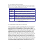
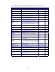
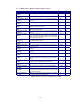
6.2 Static Display Screen Error Messages
During the weld cycle the WC 1 controller performs diagnostic checks on the system and control
inputs. If an error occurs the WC 1 will display the error message on the second line of the static
message screen. The following is a summary of the error messages:
DISPLAY ERROR MESSAGE DESCRIPTION
SCHED 1
READY!
No Errors. Normal static message screen displays active schedule number.
PGM EVENT
ERROR!
Program Event Error indicates the active weld schedule has an invalid event
enabled. Error is automatically reset when Cycle start is cleared.
POWER NOT
READY!
Power supply not ready error indicates the Power supply ready input is not
asserted. This error will occur when the Cycle start is asserted and the Ready
input is not active. Error is reset when Cycle start is cleared.
ARC ACTIVE FAIL! The Start parameters are being ramped to the run level and the Ramp time delay
is active.
SCHEDULE
FAULT!
Schedule Fault Error indicates the active weld schedule has an invalid
parameter. This error will occur when an out-of-range parameter is detected
during a weld cycle. Error is automatically reset when Cycle start is cleared.
**SYSTEM
ESTOP**
ESTOP message indicates that the WC 1 controller has been forced into a
Emergency stop condition by clearing the WC1 ESTOP input. When the ESTOP
mode is active all WC 1 outputs and weld events are cleared. The only recovery
is to assert the ESTOP input signal.
Table 2 - Displayed Error Messages
6.3 Modifying Weld Schedule and System Parameters
The WC 1 Control provides two methods for programming a weld schedule. The first method is to
use a PC and the RS-232 serial port to program the schedules off line. Refer to Section 7.0 for
additional information on serial off-line programming. To create, modify or load a schedule set the
front panel key-lock switch to the “PROGRAM” position. The WC 1 will display the “WELD
PARAMETER" menu option. Select this menu by pressing the “SEL” button. To change the Control
configuration parameters press the “INC” or “DEC” button. The WC 1 will display the “
CONFIG
PARAMETER
” menu option. To select a specific menu option, press the “SEL” button. After
selecting a menu option the WC 1 will display the menu items and their current values on the
display. To move forward through the menu items press the “
INC
” button. To move back to the
previous menu item, press the “
DEC
” button. When moving through the menu items the WC 1 will
display the current value for each of the items selected. To change any selected item press the
“SELECT” button. A Blinking cursor will be displayed. To increase the displayed value, press the
“
INC
” button. To decrease the value, press the “
DEC
” button. To exit the edit routine press the
“SELECT” button. The Blinking cursor will be cleared from the display. Move to the next item by
pressing the “INC” or “DEC” buttons. To exit the schedule, edit routine turn the key-lock switch to the
“RUN” position. If a value has been modified, by pressing the “SELECT” button, the display will
show a “SAVING SCHEDULE” prompt indicating that the changes have been saved to the WC 1
nonvolatile Memory. The Display will then return to the normal Static display messages.