Extend-A-Page VHF Transmitter System Manual EAGLE BROADBAND, INC. 101 Courageous Drive League City, TX 77538 Telephone: (281) 538-6000 Fax: (281) 334-5302 Toll Free: 1-800-628-3910 www.eaglebroadband.
Table of Contents Page Preface. i Limited Warranty iii 1 Introduction 1-1 Transmitter 1-2 General 1-2 2 Specifications 2-1 2.1 VHF Exciter 2-1 2.2 General 2-1 3 Installation 3.1 Safety Regulation 3-1 3-1 3.1.1 FCC Requirements 3-1 3.1.2 FCC Interference Warning 3-1 3.1.3 OSHA Safety Standards 3-2 3.1.4 Lighting Protection Consideration 3-2 3.1.5 Integrated Circuit Handling Procedure 3-3 3.1.6 Equipment Unpacking & Inspection 3-3 3.
4.2.1.1 Circuit Description 4-2 4.2.1.2 Frequency Determining and Stabilization 4-3 4.2.2 Exciter Board Circuit Description 4.2.2.1 Channel Phase-Locked Loop (PLL) 4.2.2.2 Upconverter 4-4 4-4 4-6 4.3 Front Panel Display Board 4-8 4.
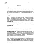
Preface Preface Scope The Extend-A-Page Technical Manual contains detailed information regarding the system installation and technical description of the Extend-A-Page receiver and transmitter. The scope of this document is to provide the reader with a general understanding of the system and features of the Extend-A-Page system. The user of this manual should have a background with similar types of equipment. Copyright This document contains proprietary information protected by copyright.
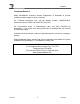
Preface Customer Service Eagle Broadband’s Customer Service Department is dedicated to provide complete product support to all its customers. For Technical Assistance only, call the toll-free number 1-800-628-3910, between the hours of 8:00 A.M. and 5:00 P.M. (CST). For non-business hours or International’s calls, call (281) 538-6000 for instructions. If you reach voice mail, please leave a message and your call will be returned promptly.
Warranty Limited Warranty 1. The product line of paging and mobile equipment, base stations/power amplifiers, receivers, transmitters, security and transmitter control equipment sold by EAGLE BROADBAND INTERNATIONAL, INC. is warranted to the original buyer to meet the then current published specifications, drawings and/or such modifications thereof as Buyer and Seller have agreed to in writing and to be free from defects in workmanship and materials.
Warranty 4. The Seller shall have the right of final determination as to the following: (a) existence of cause and defect, (b) whether adjustment will be allowed, and (c) if allowed, whether adjustment will be by repair or replacement. When adjustment is not allowed, a reasonable charge will be made to the Buyer to cover the Seller’s cost of inspection and handling.
Introduction 1 Introduction The new Extend-A-Page VHF Transmitters specifically designed for use as a high quality exciter to Eagle’s low and high power transmitters. In addition, the Extend-A-Page VHF Transmitter can be used as an exciter for non-Eagle Wireless International Transmitters. Furthermore, the Extend-A-Page can be used to provide fill-in coverage in those locations where normal paging service from a citywide paging system is not adequate.
Introduction The Extend-A-Page VHF Transmitter features are: Transmitter • VHF Digital Transmitter (fully synthesized) • Continuous Duty Operation • Fully Shielded and Filtered Packaging • Power Outputs Adjustable up to 400 Milliwatt General • Convenient Desktop or Rackmount Enclosures with • • • • Version 4 Receiver and Transmitter Separately Packaged Standard AC Power Connections Convenient Rear Mounted RF Input and Output Connections Interconnect Between Receiver and Transmitter Sections on a DB 9 Co
Specifications 2 Specifications 2.1 VHF Exciter Frequency Band Frequency Generation Power Output Channels Channel Spacing Channel Bandwidth Emission Designators Frequency Stability 150 – 174 MHz Synthesized 400 Milliwatt 1 (standard), 4 (optional) 7.5 KHz Narrowband (12.5 kHz) 11K0F1D, 11K0F3E ± 20 ppb, -30 °C to +60 °C ambient ± 60 ppb per year, long term aging Analog or Digital 61/94/121/182 µS, selectable Analog, ±2.4 KHz Digital, ±2.
Installation 3 Installation 3.1 Safety Regulation 3.1.1 FCC Requirements FCC Regulations state that: 1. Radio Transmitters may be tuned or adjusted only by persons holding a general class commercial radiotelephone operator’s license or by personnel working under their immediate supervision. 2. The RF power output of a radio transmitter should be no more than that required for satisfactory technical operation considering the area to be covered and local conditions. 3.
Installation 3.1.3 OSHA Safety Standards The United States Department of Labor, through the provisions of the Occupational Safety and Health Act, has established an electromagnetic energy safety standard with applies to the use of this equipment. Proper use of this radio will result in exposure below the OSHA limit. The following precautions are recommended: DO NOT operate the transmitter of a fixed radio (base station, radio paging transmitter RF equipment) when someone is within two feet (0.
Installation • • Tie all equipment ground together to a single point. Then, ground that point to a grounding rod using as short and as straight a ground wire as possible. The ground wire must be bundled with other wires in the system. Also, ground wires must not run along a metal plane. 3.1.5 Integrated Circuit Handling Procedure Care should be taken in handling the circuit boards during installation and service.
Installation 3.2 Installation Procedure 1. Connect antenna to the Extend-A-Page transmitter. The Transmitter unit is equipped with a N Female connector. 2. Connect a power cable from the transmitter unit to the AC power outlet. Ensure that the AC outlet is grounded. 3. Connect the paging terminal or controller outputs to the DB9 connector labeled transmitter interface. 4. If an Extend-A-Page receiver is used, use the DB9 connector for interface to the Extend-A-Page transmitter.
Technical Description 4 Technical Description 4.0 Overall System The Extend-A-Page VHF transmitter consists of: 1. Control “U” Board 2. Control “A” Board 3. Synthesized Exciter 4. Front Panel Display Board 5. Power Supply The overall control system is shown in the Overall Block Diagram Page A20. The Control “U” board in Fig. 3-D handles the frequency setup of the RF exciter and the modulation on the 10.7 MHz I/F.
Technical Description deviate the NCO to generate the instantaneous signal for the 10.7 MHz I/F. The maximum deviation is limited to +/- 5 KHz. In the digital mode the MFSK data will be sent two bits at a time to the Hi Stability exciter along with data clock, or just one bit of data and clock when in the FSK mode. After the key line is deactivated, the microprocessor sends the debounced inactive key line to the RF exciter and sets the RF exciter center frequency to the default center frequency selection.
Technical Description 4.3 EXTEND-A-PAGE TRANSMITTER UNIT EXCITER The exciter module of the Extend-A-Page VHF transmitters utilizes advanced direct digital synthesis techniques to achieve ultra-high stability analog composite modulation or a two and four level FSK output at modulation rates 3200 baud (2 Level) and 6400 baud (4 Level) depending on the selected mode configuration. The Extend-A-Page exciter is divided into two parts: the exciter control board and the exciter board. 4.3.
Technical Description frequency is set by the manufacturer, and can only be changed by installing another PROM that has the new data written into it. The “Program Data” data stream is determined by the formulas shown in Appendix page A-47, Figure 9. These Formulas determine the Program Reference Counter and Comparative Frequency Multiplier Values sent to set the desired frequency.
Technical Description Frequency Synthesizer The frequency synthesizer is used to stabilize the source for the carrier (139.3 to 163.3 MHz) phased-locked to stable reference frequency of 3 MHz, supplied from the reference PLL. Hence, the carrier frequency will be very stable. The frequency synthesizer is realized with a single integrated circuit. The frequency synthesizer divides the reference frequency of 3 MHz from the reference PLL. The amplified feedback of the output signal from the VCO (139.3 – 163.
Technical Description Loop Filter The loop filter is a low-pass filter, which is designed to give the phase-locked loop the desired characteristics in response to transient change in the output voltage from the frequency synthesizer. The low-pass filter is realized as a passive filter. The filtered output signal controls that output frequency of the VCO. Voltage-Controlled Oscillator (VCO) The VCO generates an output frequency of 139.3 to 163.3 MHz.
Technical Description in the VCO. In this way, the output voltage from the phase detector controls the output frequency of the VCO. DC-Offset Amplifier The DC-offset amplifier offsets the output voltage from the phase detector. The amplifier is realized with an integrated circuit, containing two operational amplifiers. The DC-offset amplifier is fed with an analog voltage. The first amplifier is configured as a DC voltage follower. The second amplifier is configured as a differential amplifier.
Technical Description Amplifier (before Mixer) The amplifier is used to amplify the RF signal before it is mixed with the signal from the channel PLL. It also provides isolation for the previous blocks. Mixer In the mixer, the carrier (139.3 – 163.3 MHz) from the channel PLL and the decoupled RF signal (150 – 174 MHz) are mixed. In this way an intermediate frequency (IF) of 10.7 MHz ± deviation is obtained.
Appendices A Extend-A-Page Appendix Figure 1 – A 150 MHz Exciter Control Board (Four Level FSK 10.7 MHz NCO A-3 Figure 1 – A 150 MHz Exciter Control Board (RF Output Amp 10.
Appendices Figure 8 – B Exciter Layout (Bottom) A-31 Figure 8 – B Exciter Layout (Top) A-32 Figure 8 – C Exciter Bill of Material A-33 Figure 8 – D Exciter (FLX150-VCO (CW)) Layout A-42 Figure 8 – D Exciter (FLX150-VCO (CW)) BOM A-43 Figure 8 – E Exciter (FLX150VCO (MOD)) Layout A-45 Figure 8 – E Exciter (FLX150-VCO (MOD)) BOM A-46 Figure 8 – F Exciter Block Diagram A-48 Figure 8 – G Exciter Board Alignment Procedure A-49 Figure 9 Frequency Data Stream A-50 Figure 10 PLL Block
B C D U3 +12V C26 + C25 4.7uF GND 5 1 TP3 3 +5V 4.7uF 5 C35 + C27 C28 0.01uF 0.01uF +2.5V 0.01uF EN OUT NR/ADJ 4.7uF VCC IDTB0 +3.3V 4 C36 C37 0.01uF FERRITE 4.7K RN5 +5V 1 2 3 4 2 3 4 1 2 3 4 C38 IDTB1 4.7uF 0.01uF P2 C14 0.01uF 0.01uF 0.01uF 5 6 2 1 2 3 4 8 7 6 5 1 2 3 4 8 7 6 5 RN4 4.7K GND +12V +12V BTX_CONT PLL_STB PALCLK PGMDATA XIN_STB UNLOCK1 UNLOCK2 LK_CNTL GND +3.
A B C TP1 D +3.3V +3.3V BYPASS CAPS 4 C10 + C11 47uF + 47uF C190 C15 C16 C17 0.1uF 0.01uF 0.01uF 0.01uF GND VCC C18 0.01uF TP4 47 R118 P1MHZREF U1 33 BRESETL 33 R14 1MHZREF 470K C7 0.1uF + 4 5 GND 3 C8 C9 47 7 9 330 470K R12 6 8 R16 R15 10uF C20 C21 C22 C23 C24 0.01uF 0.01uF 0.01uF 0.01uF 0.01uF 0.01uF 4 C501 R117 P1MHZFB C19 GND +3.3V R13 E 0.01uF 10 GND 11 +3.3V 12 +3.3V 18 RST Q0 FEEDBK REF SEL SYNC0 +3.
B C 1 E MH4 1 MH6 4 1 MH5 4 MH3 D 1 MH2 1 MH1 1 A GND GND +3.3V +3.3V 3 +3.3V TX_MOD + 2 R406 1 11 R403 SMA_5 3300pF R405 LT1499/SO14 9.1K 9.1K C403 47K 10K R510 U14B 4 3 5 + 6 11 U14A 4 BIAS_MID J5 +3.3V C404 4700pF R407 R408 9.1K 9.1K C405 7 LT1499/SO14 3300pF AGND AGND 10 + 9 - 4.7uF + FAUDIOIN LT1499/SO14 1800pF AGND AGND AGND R506 + 4.7uF C406 TP7 8 AGND C401 U14C 4 C402 11 R402 47K 3 +3.
A B C D J7 GND 110 PREGSEL1 109 PREGSEL0 I/O70 I/O69 PCNFNCO6 PCNFNCO5 PCNFNCO4 PCNFNCO3 PCNFNCO2 +3.3V PCNFNCO1 PCNFNCO0 PWSSTRB PWBYTSTRB 120 119 118 117 116 115 114 113 112 111 130 PWS1 129 GND 128 PWS0 127 +2.5V 126 TPSEL2 125C40MHZ 124 PRESETL 123 GND 122 P1MHZFB 121 PCNFNCO7 I/O83 GND I/O82 VCC INPUT4 globalCLK2 INPUT3 GND I/O81 I/O80 BSHDT0 GND BMFSKH BCFOVRH BDIGMODEH BCNFREG +3.3V PWS4 PWS3 PWS2 140 139 138 137 136 135 134 133 132 131 C304 R502 3.9K 0.01uF GND R501 3.9K 1 C305 0.
Appendices FIGURE 1-C – 150 MHZ EXCITER CONTROL BOARD BILL OF MATERIAL EWI Number 100106-021 100106-030 100106-032 100106-033 100106-035 100106-036 100106-042 100106-062 100106-068 100106-102 100106-117 100106-118 100106-119 100106-121 100106-122 100106-123 100106-124 100111-006 100111-009 100111-011 100111-016 100111-034 100111-056 100111-059 100111-078 100111-087 100111-089 100111-099 100111-100 100111-101 100111-111 100111-112 100111-114 100111-115 100111-117 100111-121 100128-004 100128-005 100128-034 1
Appendices EWI Number 100130-833 100135-009 100160-004 100160-030 100160-043 100111-112 100111-113 100111-118 100111-119 100111-120 100111-121 100111-122 100111-123 100112-007 100130-500 100155-102 100155-109 100155-308 100155-309 100155-311 100155-402 100155-403 100155-431 100155-508 100155-512 100155-804 100155-811 100156-800 185106-006 Version 4 Description Conn, RF, SMA, Str Jack, SMT, Receptacle Crystal, Ovenized, 10.000MHz Ferrite, Bead, 170 ohm @ 100MHz, 0805 Inductor,4.
Appendices FIGURE 1-D – 150MHz EXCITER CONTROL BOARD BLOCK DIAGRAM BUFFER CLK LOGIC SEQUENCER 1 MHz REF CLK CRYSTAL 10 MHz REF 10 MHz REF 10.
Appendices FIGURE 2 OVERALL BLOCK DIAGRAM HI STAB EXCITER MODE CONTROLS DIGITAL DATA 10.7 MHz RF EXCITER DATA DIGITAL KEY ANALOG KEY RF OUT REF SETUP DATA CONTROL U TX_MOD STDATA SC[3..
12/28V FANV1 FANV2 +5V GND +5V GND +12V -12V 3 UNUSED5 LCD_RS LCD_RW LCD_EN LCD_DAT0 LCD_DAT1 LCD_DAT2 LCD_DAT3 LCD_DAT4 LCD_DAT5 LCD_DAT6 LCD_DAT7 RFIN_SIG LOPWR_LED ALARM_LED DRIVE_ADJUST UNUSED16 +5V GND PA CONTROL 1 1 2 3 4 5 6 7 8 9 10 11 12 13 14 15 16 17 18 19 20 21 22 23 24 25 26 27 28 29 30 31 32 33 34 35 36 37 38 39 40 41 42 43 44 45 46 47 48 49 50 51 52 53 54 55 56 57 58 59 60 61 62 63 64 +5V GND +12V -12V +12VAR STDDATA DKEYLED UNUSED1 SYSLED UNUSED2 BDIGKEY BDIGDATA BDICLK1 BDICLK2 UNUS
Appendices FIGURE 3-C – BACKPLANE BOARD BILL OF MATERIAL EWI # 100001-111 100105-005 100105-014 100110-009 100110-015 100110-167 100110-170 100110-204 100116-001 100120-202 100130-046 100130-077 100130-109 100130-175 100130-500 100130-500 100130-501 100130-501 100130-509 100155-829 100155-830 189004-007 Version 4 Description U of M Qty Fuse, 7 Amp, PICO II, 125V, Axial Lead Cap, 1uF, 35V, Tantalum, Radial 10% Cap, 10uF, 35V, Tantalum, Radial 10% Res, 330 Ohm, 1/4W, CF, 5% Res, 604 Ohm, 1/4W, Carbon Fil
Appendices FIGURE 3-D – BACKPLANE BOARD BLOCK DIAGRAM SIGNAL INPUT POWER INPUT Version 4 BACKPLANE BOARD A-15 OUTPUT 4/2/04
A B C D E +5V R1 R2 10K R3 0 U1 U2 10K 1 2 BBCLK 4 5 6 R4 4 BMFSKH 20 21 22 23 24 25 TMS BRNDH BSHDT1 SCL SC0 SC1 SDA BSHDT0 +5V U3 DIGKEY 2 D1 DICLK1 1N914 1K R8 INT 10 9 DICLK2 SC2 SC3 AKEY D2 1N914 +5V GND R9 +5V +5V +5V 14 15 +5V +5V +5V GND STDDATA DKEYLED +5V DIGKEY HOTKEY AKEY FREQ0 FREQ1 FREQ2 SC0 SC1 SC2 R11 10K R12 10K R13 10K R14 10K R15 10K R16 10K R17 10K AKEY TX_CONT 2 1 CDATA RESET M.O.
Appendices FIGURE 4-C – CONTROL U BOARD BILL OF MATERIAL LINE NO. REFERENCE DESIGNATION 1 2 C1, C2, C3, C4, C5, C6, C7, C8, C11, C12, C13, C14, C15, C16, C19, C20, C21 C9 3 QTY EWI PART NO. MFG. Part No. Cap, 0.1uF, 50VDC, Polyester film, ±5% Panas- ECQB1H104J Digi Key P4593-ND 1 Cap, 47uF, 16V, Tantalum, Electrolytic, ±20% C10 1 Cap, 4.
Appendices FIGURE 4-C – CONTROL U BOARD BILL OF MATERIAL (2 of 2) REFERENCE DESIGNATION LINE NO. QTY EWI PART NO. Description MFG. Part No. 21 SW3 1 100001-006 Switch, Push Button, Rt Angle PCB Mount, SPDT EP11SD1AVBE 22 U1 1 CMOS/TTL Oscillators Epson - SG-51P 8.
Appendices FIGURE 4-D – CONTROL U BOARD BLOCK DIAGRAM MODE CONTROL DIP SWITCH 8 KEY LINE BACKPLANE DATA 2 CLOCK I/F BUFFERS BKEY BDAT A BCLK MODE CONTROL 5 2 ALTERA LOGIC ADATA 2 ACLK HI STAB CONNECTO R VIA BACKPLANE KEY BACKPLANE FREQ SEL LED 3 AT89LS 8252 µP 4 BACKPLANE TX - KEY SC0-SC3 4 5 LED DISPLAY Version 4 A-20 4/2/04
1 2 3 4 5 OPTION 6 7 8 OPTION GUARD TONE FILTER/DETECTOR NOTCH FILTER (300HZ-20KHZ) JP9 1 1 AUDIOIN+ 5K 1 AUDIOIN- 2 15 16 L1 RFC L2 1 2 T1 2 1K 3 6 RP31 1K 5 2 3 14 11 6 4 1 16 9 8 SC0 SC1 SC2 SC3 U2 S1 S2 S3 S4 D1 D2 D3 D4 IN1 IN2 IN3 IN4 V+ VGND C54 .1uF + .001uF U3A 2 TP3 GND +5V R13 TL074 U4 OUT TIMR FLG TIMC LOWF B 4.7K 8 1 C12 4.7uF 2 XR567 + C11 .47uF 1 DATA MODEM .1uF TL074 R35 2.5M 1 +12V TP6 1 3 C26 4 10k 100pF R2 2 15 10 7 C48 .
Appendices FIGURE 5 –B – CONTROL A BOARD LAYOUT Digital Data Offset Digital Data Dev. Analog Data Dev.
Appendices FIGURE 5 – C – CONTROL A BOARD FLOW DIAGRAM Input Audio Audio Transformer Audio Buffer Dig Control Switch Analog Modulation Buffer Digital Modulation Dig Data Offset And Dev Control Modulation To Exciter Inverted Digital Data From Control D Version 4 A-23 4/2/04
NFS25 SERIES Dual and triple output • • • • • • The NFS25 series is a 25W universal input AC/DC power supply on a 5 x 3 inch card with a maximum component height of 1.2 inches for use in 1U applications. The NFS25 series is available with a wide range of models in the industry standard 5 x 3 inch footprint and has proven itself to be reliable and versatile product for a wide range of communication and industrial applications.
LOW TO MEDIUM POWER AC/DC POWER SUPPLIES | 25W AC/DC 25 Watt AC/DC universal input switch mode power supplies OUTPUT CURRENTS OUTPUT VOLTAGE MIN +5.1V (IA) 0A 2.0A 5.0A 50mV ±2.0% +12.0V (IB) 0A 1.5A 3.0A 120mV ±5.0% –12.0V 0A 0.2A 1.0A 120mV ±5.0% +5.1V 0A 3.0A 5.0A 50mV ±2.0% +12.0V 0A 0.2A 1.0A 120mV ±2.0% –12.0V 0A 0.2A 1.0A 120mV ±2.0% +5.1V (IA) 0A 2.0A 5.0A 50mV ±2.0% +12.0V (IB) 0A 1.5A 3.0A 120mV ±5.
Appendices FIGURE 7 – DISPLAY BOARD FIGURE 7-A – DISPLAY BOARD SCHEMATIC P3 - 14 DATA LED P3 - 4 D KEY LED P3 - 4 SYS LED P3 - 5 A KEY LED 1 U1 2 9 U1 8 R4 330 Ω R2 330 Ω U1 R7 330 Ω 3 U1 4 11 U1 10 R1 330 Ω R3 330 Ω P3 - 26 +5V DATA DKEY SYS AKEY POWER U1 P14 C5 0.
Appendices FIGURE 7-B – DISPLAY BOARD LAYOUT 285100-000 LED BD. ASSY.
Appendices FIGURE 7-C – DISPLAY BOARD BILL OF MATERIALS Bill Number Item Number Description Description U of M Qty 100105-019 100105-527 100110-009 100120-201 100120-202 100130-501 100131-003 100155-311 185800-000 Cap, 100uF, 16V, Tantalum Radial, 10% Cap, 0.
Appendices FIGURE 7-D – DISPLAY BOARD BLOCK DIAGRAM LED, DKEY DIGITAL KEY DIGITAL DATA ANALOG KEY SYSTEM Version 4 BUFFER LED DRIVER A-29 DATA AKEY SYS 4/2/04