
User Manual


Appendices
Version 4 A-49 4/2/04
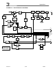
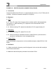
FIGURE 8-G – EXCITER BOARD ALIGNMENT PROCEDURE
1. Connection
Connect the cables from RF unit to J1 (signal and power source), J3 (10.7 MHz) and J4
(10 MHz). Connect a modulation analyzer to J2 (output).
2. Alignment
2-1 VCO
2-1-1. Use a PLL data of the frequency that is actually used for data transmission.
Turn power on. While monitoring TP1, adjust the core of the channel VCO for
approximately 4V.
2-1-2. While monitoring TP2, adjust the modulation VCO for approximately 4V.
2-2 Modulation
2-2-1. While monitoring TP3, adjust RV1 for 8,5V.
2-2-2. While monitoring a modulated waveform, adjust RV2 for a point where the
waveform is sharp and no noise overlapping exists.
2-3 Output Power
While monitoring the output power on the modulation analyzer, adjust RV3 for 0.3W
output.
3. Verification
3-1. Make sure that the frequency used for alignment is the one that will actually be
used for data transmission.
3-2 Make sure that the frequency deviation is less than ±5 KHz.