
Instruction Sheet

Page 5
THIS ALARM WILL NOT WORK WITHOUT 120 VAC POWER AND A GOOD
BATTERY PROPERLY INSTALLED. THE ALARM SHOULD BE TESTED WHEN
INSTALLED AND THEN TESTED WEEKLY AFTER THAT.
INSTALLATION INSTRUCTIONS: CAUTION!! READ CAREFULLY.
Installation of this alarm must conform to the electrical codes in your area; Article 760 of the
National Electrical Code, NFPA 72, 101; SBC (SBCCI); UBC (ICBO); NBC (BOCA): OTFDC
(CABO), and any other local or building codes that may apply. Wiring and installation must
be performed by a licensed electrician. Failure to follow these guidelines may result in injury
or property damage.
This alarm must be powered by a 24-hour, 120V AC 60Hz circuit. Be sure the circuit cannot be
turned off by a switch, dimmer or ground fault circuit interrupter. Failure to connect this
alarm to a 24-hour circuit may prevent it from providing constant protection.
IMPORTANT: Do not subject this alarm to megger, high voltage or high-pot tests. Remove the
alarm(s) before high-potting tests occur on the circuit or system. (Ref. Section 550-17, National
Electrical Code, 2002 Edition).
ELECTRICAL SHOCK HAZARD
Turn off power to the area where you will install this alarm at the circuit breaker or fuse box
before beginning installation. Failure to turn off the power before installation may result in
serious electrical shock, injury or death.
CAUTION: THIS CO AND NATURAL GAS ALARM IS SEALED. THE COVER IS
NOT REMOVABLE!
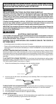
• A mounting bracket is provided on the back of the alarm.
• Remove the mounting bracket from the back of the alarm by holding the mounting bracket and
twisting the alarm in the direction indicated by the "TWIST TO REMOVE" arrow on the side of the
alarm base.
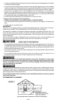
OPTIONAL TAMPER RESISTANT FEATURES: There are two separate tamper resistant locking
features provided for this model. Activating one or both of these features deters someone from
removing the alarm from the mounting bracket or removing the battery from the alarm. The breakaway
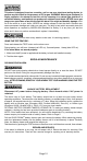
locking pins are clearly marked and molded into the mounting bracket. Refer to the diagram on the
next page.
TO ACTIVATE THE LOCKING FEATURES: Do not activate the locking features until you have
activated the battery, mounted the alarm to the bracket and tested the alarm. Refer to OPERATION,
TESTING & MAINTENANCE instructions on Page 6.
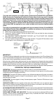
1. Detach the breakaway alarm locking pin from the mounting bracket.
ALARM/BRACKET
LOCKING PIN
BATTERY LOCKING PIN
TO DEACTIVATE THE LOCKING FEATURES: To remove the alarm for cleaning or servicing or to
replace the battery, you must first remove the appropriate locking pin, if it has been installed.
1. Turn off AC power to the circuit.
2. Use long nose pliers to pull the locking pin out of the hole.
3. It is now possible to remove the alarm or replace the battery.
WIRING INSTRUCTIONS:
1. a. The appropriate power supply is 120 Volt single phase power supplied from a non-switchable
circuit NOT protected by a ground fault circuit interrupter.
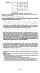
2. Insert the pin into the hole for the feature you are activating. Refer to the diagram below for
correct placement.
INSERT ALARM
LOCKING PIN HERE
INSERT BATTERY
LOCKING PIN HERE