
Use and Care Manual
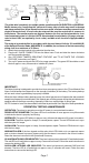

The yellow wire is used only for multiple station operations with USI ELECTRIC or UNIVERSAL
Model alarms only. Connecting this yellow wire to any other circuits may result in damage
and alarm malfunction. When alarms are interconnected, all alarms must be powered from a
single AC branch circuit. If local codes do not permit, be sure the neutral wire is common to
both phases. The maximum wire run distance between the first and last alarm/device in an
interconnected system is 1,000 feet. NOTE: Use standard household wire (18 gauge or larger,
rated at least 300V, as required by local codes) available at all electrical supply/hardware
stores.
The wiring to be used shall be in accordance with the provisions of Articles 210 and 300.3(B)
of the National Electrical Code, ANSI/NFPA 70. In addition, the resistance of the interconnecting
wiring shall be a maximum of 10 Ohms.
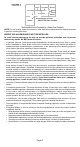
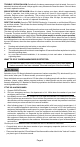
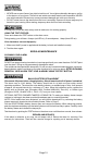
2. Attach the mounting bracket to the electrical junction box.
3. Plug the AC QUICK CONNECTOR into the alarm base. Push and twist the alarm clockwise
onto the mounting bracket.
4. See "OPTIONAL TAMPER RESISTANT FEATURE" and "TO ACTIVATE THE LOCKING
FEATURE" instructions on Page 5.
5. Turn on AC power and check the LED's for proper operation. The green LED should be on and
blink off approx. every 20 seconds to indicate AC power.
Page 7
IMPORTANT!
The battery backup is designed to provide short-term emergency power to the CO and Natural Gas
Alarm. Actual backup time depends on the strength (freshness) of the battery. The battery backup
will not work unless a good battery is properly installed.
When the alarm utilizes battery backup power, the natural gas sensor will operate the alarm and will
sample less frequently to extend battery life. Natural gas could be present during this period between
samples without the alarm sounding, especially if there is a rapid buildup of natural gas.
NOTE: It is best to “reset” the alarms before initial test is performed. See Page 9 for Reset procedures.
120 VAC 60Hz
100mA Max.
OPERATION, TESTING & MAINTENANCE
OPERATION: The alarm is operating once the AC power is connected and turned on.
READY/ACTIVE CONDITION: The green LED is on and blinks off once approx. every 20 seconds
to indicate the alarm is properly functioning.
GREEN LED: The green LED blinks on approx. every 40 seconds whenever AC power is turned on.
CO ALARM: The alarm signal is 4 beeps, 5 second pause, repeat. The red LED blinks on in sync
with the cycle of 4 beeps.
GAS ALARM: The alarm signal is 1 beep, 2 second pause, repeat. The blue LED blinks on in sync
with the horn beep.
NUISANCE ALARM: If the horn signals and the red or blue LED’s blink on for no apparent reason
and no obvious hazard is present, please verify that the alarm is mounted in the correct location.
Reset the alarm as instructed in the Operational Summary.
CO ALARM LATCHING LED INDICATOR: The alarm had previously detected CO and had alarmed.
The red LED is off and blinks on approx. every 5 seconds until reset. Follow the reset instructions to
remove the latching LED.
GAS ALARM LATCHING LED INDICATOR: The alarm had previously detected GAS and had
alarmed. The blue LED is off and blinks on approx. every 5 seconds until reset. Follow the reset
instructions to remove the latching LED.