
Operating Instruction


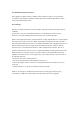
Table Of Contents

7 / 8
Wiring for automatic door Installation notes
1. When arrange the wires, if the 12V power supply cable of the host does not adopt the “Special power
strip” and is in long distance, resulting in large resistance, then abnormal phenomena may occur easily such
as insufficient voltage (≤11V), repeat restart, system crash and so on. Wiring connection of voltage
metering is shown as follow.
2. Power adapter (brought with the device) of different countries are optional, such as European standard,
American standard, British standard and so on.
System installation schematic drawing for automatic door
Wiring schematic drawing for sensor switch of automatic door
Auto-door controller
+ assembly units
Relay interface
Sensor (inside)
~110- 240V
DC12V Ethernet
Host
Opening signal PUSH
Public end GND
12V
Controller of auto-door (only used terminals will be listed)
Ethernet
DC+
DC-
NO
COM
Sensor
DC+
DC-
NO
COM
NO
COM
Host
12V
GND
Power
Relay
Power
GND
12V
Cable equivalent
resistance1
Cable equivalent
resistance2
Voltage meter
V
Host
Extension of power cable (weak current) can not exceed 2m, otherwise, it may cause insufficient
power supply for the host end, and abnormal phenomena like repeat restart, system crash and so
on may occur. If the power is far away from the device, the power cable can be extended (strong
current).
If use other power adapter, 9V 1A as an example, then insufficient voltage and too weak current
may cause repeat restart.
The cable cannot be too fine (such as network cable and fine line), it is suggested to connect
multi-strand cable in parallel or use copper core bold cable, to ensure voltage >11V.
Attention: If use network cable, the extension cable uses 4-strand cable as positive pole and 4-strand cable as negative pole.
If not clear with how to extend, please contact the provider to change “Special power strip”.
Wiring connection