
Technical data

Repair
7-12
P/N 7135049A
E 2007 Nordson Corporation
VBC_Siemens
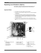
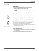
Replacing Level Evaluator (Option)
The evaluator is located on the back wall of the electrical cabinet. The
active measuring range is indicated by two lines on the level sensor.
Important Notes
S The length of the sensor cable may not be changed.
S Adjustment by electrostatically charged persons can cause the amplifier
to malfunction.
S All adjustments should be made with operating ground (no ground
conductor function) connected. The operating ground must be linked to
the metal casing of the melter along the shortest path. Do not connect
via ground conductor!
S All potentiometers have 20 revolutions and no mechanical limit stop,
meaning no fixed end position. They can not be damaged by turning too
far.
1
9 8
6
7
12
13
10
11
1
3
2
3
4
2
5
14
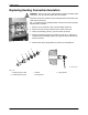
Fig. 7-17
1 LED Operating voltage (green)
2 Potentiometer 1
3 LED Calibration
4 Jumper Calibration
5 Potentiometer 2
6 LED Tank overfilled (red)
7 LED Level (green)
8 LED Tank empty (yellow)
9 LED Reference section (green)
10 Coaxial connection Sensor
(black)
11 Coaxial connection Sensor
(white)
12 Connection Operating ground
13 Signal output
14 Voltage supply (24 V)