
Technical data


Left
Right
Repair
7-15
P/N 7135049A
E 2007 Nordson Corporation
VBC_Siemens
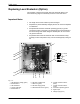
Calibrating
Prerequisites
S Level sensor is installed, fastened mechanically and connected
electrically (observe color coding of sensor cable)
S Tank is empty (empty calibration: most sensitive setting, material
irrelevant)
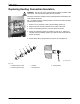
S Operating voltage is applied (LED Operating voltage (1) lit).
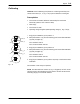
Sensor Break
1. Turn potentiometer A (3) 20 revolutions counterclockwise.
2. Turn potentiometer P3 (2) counterclockwise until the green LED empty
(5) is off and the red LED full (6) begins to flash.
3. Turn potentiometer P3 counterclockwise to the switching point (green
LED empty on, red LED full off).
4. Then turn counterclockwise one or two more revolutions past the
switching point.
NOTE: The closer the setting is to the switching point, the more precise is
the measurement. When the potentiometer P3 is turned all the way
counterclockwise, sensor break monitoring is deactivated.
5. Perform function test: Disconnect sensor cable; sensor break monitoring
is triggered (red LED full flashes).
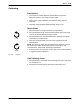
Fig. 7-20 Direction
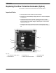
Limit Switching Points
1. Turn potentiometer A clockwise to the switching point (green LED empty
off, red LED full on).
2. Turn back from switching point until the green LED empty is on.