
Technical data
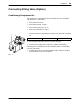

Outputs
Inputs
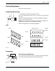
Installation
3-10
P/N 7135049A
E 2007 Nordson Corporation
VBC_Siemens
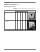
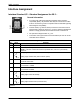
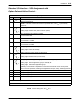
Interface Assignment
Interface Standard I/O − Standard Assignment for XS 2 −
General Information
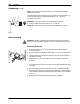
S To conform with a European standard regarding electro-magnetic
compatibility (EMC), only shielded cable may be connected. The cable
must be connected to ground in compliance with the standard regarding
electromagnetic compatibility.
S Inductive loads (e.g. solenoid valves) connected to the melter must be
equipped with a protective device (e.g. recovery diode) that disables the
inductive voltage generated when an inductive load is switched off.
S The permitted voltage deviation is 10%.
S In Field bus mode (option Field bus communication) the unit can not be
controlled via the interface.
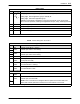
Digital inputs
Pin Input Function
1* 24 V
DC
Internal (melter)
2* 0 V
DC
External (customer’s)
NOTE: Customer connects his reference potential here, if 24 V
DC
is provided by
customer.
3
0 V
24 V
Rising edge: Heaters ON (main contactor closes)
0 V
24 V
Falling edge: Heaters OFF (main contactor opens)
4 24 V: Both motors ON (collective enable)
0 V: Both motors OFF
5 24 V: Enable Motor 1
0 V: No Motor 1 enable
6 24 V: Enable Motor 2
0 V: No Motor 2 enable
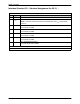
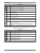
9
0 V
24 V
Rising edge: Switch on Standby
0 V
24 V
Falling edge: Switch off Standby
10
0 V
24 V
Rising edge: Key-to-line mode (for both motors)
0 V
24 V
Falling edge: Manual mode (for both motors)
* optional