R-320 Automatic Round Product Labeling System Operator’s Manual Serial #
Operator’s Manual Version: C 12/8/2004 The information in this manual is subject to change without notice. No part of this manual may be reproduced or transmitted in any form or by any means, for any purpose other that the purchaser’s personal use, without prior written consent from Universal Labeling System, Inc. Universal Labeling Systems, Inc. 3501 8th Ave South, Saint Petersburg, FL 33711 Phone (727) 327-2123 Fax (727) 323-4403 Web Site: http://www.universal1.
Table of Contents SECTION 1 OVERVIEW....................................................................................4 INTRODUCTION...........................................................................4 SPECIFICATIONS ........................................................................5 PRODUCT WARRANTY ...............................................................6 PERFORMANCE GUARANTEE ...................................................6 SECTION 2 CONTROLS AND THEIR FUNCTIONS................
SECTION 1 OVERVIEW INTRODUCTION Thank you for purchasing the R-320 Automatic round product labeling system. The R-320 is known for high quality and operating convenience. The R-320 features heavy-duty steel framework with casters and leveling pads, L-15 label applicator, variable speed components, photoelectric product sensor and easy access control enclosure. The applicator is at the heart of every labeling operation.
SPECIFICATIONS Electrical Power: Label Apply speed: Label Size: Nominal Size: Shipping Weight: 120VAC, 10 Amps, 60Hz Depends on label size up to 1200 Inches/min 6-1/2” web capacity on 3” Core -12” Diameter roll 42” Wide x 72” Long x 56” Tall (1066.8mm Wide x 1828.8mm Long x 1422.4mm Tall) approx. 1075 Lbs (487.
PRODUCT WARRANTY Universal Labeling Systems, Inc. warranties all parts to be free from defects in material and workmanship for a period of one year from the date of shipment from our facility. This guarantee is based upon equipment being used 8 hours per day, or 40 hours per week, or in any increment which does not total more than a single shift operation, or 2,080 hours per year. Warranty will be reduced proportionally.
START UP SETTING CONVEYOR SPEED ______________ TURNING UNIT/ENCAPSULATOR SPEED ______________ APPLIER SPEED ______________ PRODUCT SPACER SPEED ______________ ON DELAY ______________ OFF DELAY ______________ 7
SECTION 2 CONTROLS AND THEIR FUNCTIONS R-320 CONTROL ENCLOSURE 1 2 3 4 5 6 7 Fig.1 8 1. Emergency Stop: When pressed in it shuts down the system and a Red light turns ON. To reset system, pull button back out, the Red light turns OFF, turn Main switch ON, green pilot light comes on. 2. Conveyor Switch: When on, it supplies power to the Conveyor. 3. Product Spacer Switch: When on, it supplies power to the Product Spacer. 4. Turning Unit Switch: When on, it supplies power to the Turning Unit. 5.
CONTROLS AND THEIR FUNCTIONS L-15 FRONT PANEL 1. Main Switch: Supplies power to the machine. The main switch "On" also supplies power to the hot stamp coder outlet. Therefore, the coder can be pre-heated without running the motor. 2. Fuse: 3 amps. 5 amp with coder 3. Off Delay: Turn knob clockwise to provide up to one-second delay of label detection. Works with photoelectric label sensing. 4. On Delay: Turn the knob clockwise to provide up to a one second delay before label application. 5.
SECTION 3 SETUP AND OPERATION ADJUSTING PEELER PLATE TO CONTAINER The peeler plate of the applicator needs to be adjusted square to the conveyor in both the flow direction as well as across the conveyor. To adjust in the flow direction, there is a knob under the applicator. Turning the knob clockwise will cause the applicator to tip forward. Turning the knob counter clockwise will cause the applicator to tip backwards. (See Fig.3 & 3a) Square Knob Fig.3 Peeler Plate Fig.
SETUP AND OPERATION CONTINUED 1. With power OFF, select the container to be labeled, place on conveyor for reference and adjust vertical height of guide rails. This is accomplished by loosening the ratchet handles at each guide rail mount. After adjusted, re-tighten ratchet handles. (See Fig.5) Knob Turning Unit Fig.6 Guide Rail mount FIG.5 Ratchet Handle Backing Plate Put two containers on conveyor in front of the Turning Unit. (See Fig.
SETUP AND OPERATION CONTINUED ADJUSTING THE TURNING UNIT 1. To do this, loosen the knobs under the Turning Unit. Move the Turning Unit to the desired position and re-tighten the knobs. (See Fig.8) 2. The turning unit needs to remain at a slight decline, relevant to the product flow, to the top of the conveyor (Ref. Fig. 8a). If the turning unit is inclined, the container will want to rise up off the conveyor, which will wrinkle or cause skewing to the label.
SETUP AND OPERATION CONTINUED 3. After adjusting Turning Unit height, you will also need to adjust the height and tilt of the Turning Unit Backing Plate assembly. Loosen the ratchet handles at each guide rail mount and move the assembly up or down to desired height. To adjust the tilt of the assembly, loosen the two small ratchet handles and tilt the Backing Plate assembly in or out depending on the container that is to be labeled. (See Fig.9) Small Ratchet Handles Fig.
ADJUSTING PRODUCT SENSOR CONTINUED 2. After the Product Sensor is adjusted to the container, turn power to the system on by pulling Red Emergency switch out, the Red light turns OFF, turn Main switch ON. Turn Conveyor, Product Spacer and Turning Unit switches to the OFF position, leaving the Applicator switch in the ON position. Turn OFF motor switch on the label applicator. 3. Place container under Fiber Optic Sensor. The sensor that the Fiber Optic Cable is attached to needs to be set.
ADJUSTING PRODUCT SPACER The Product spacer meters the spacing between the containers that are being labeled. The diameter of the container and the label length is what determines the spacing. If you have a 3” diameter container and a 1” long label, the spacing in between the containers would be shorter than if you had a 3” diameter container and a 9-1/2” long label for a total wrap. With power off, place a container in front of the product spacer and adjust until the container will not go past. (See Fig.
WEBBING THE L-15 1st. Turn the Applier switch on the control enclosure off. 2nd. Do not use a label to attach the web to the rewind spool; this will make the removal of the waste roll difficult. Web the machine by looking at the webbing diagram located on the side of the L-15 body. 1. Mount the label roll to the unwind hub. Push label roll straight back against the unwind backing plate. Slide the label roll retainer onto the unwind hub until it contacts the label roll. Tighten thumb screw. 2.
WEBBING THE L-15 CONTINUED 4. Route the web under the upper idler roll and peeler bar assembly tie bars, and continue between the pivot roller and peeler plate. 5. Pull the drive roll back, engage web lock link by pressing it down to release pressure on the drive roll. 6. Route the web over and around the drive roll 7. Then between the drive roll and the lower idler roll. (Silver Knurled roller) 8. Route the web back under the lower idler roll and the web stand-off stud. 9.
RUNNING THE L-15 Label stop position. Now that the machine is webbed, turn on both the main and motor switches. Slide the Web back and forth so the “label GAP” is lined up with the white dot on the sensor. Press the button on the sensor labeled “Normal”. The LEDS will start blinking and then Stop. The GREEN LED is power for the sensor. If you slowly move the label back and forth the RED LED should come on while the gap is in position.
SPECIFICATIONS SUPPLY VOLTAGE HYSTERESIS CURRENT REQUIREMENTS LIGHT IMMUNITY • 10 to 30 VDC • Polarity Protected • Minimal hysteresis promotes the detection between the backing material and the label depending on the settings • Responds to sensor’s pulsed modulated light source … • 45 milliamps (exclusive of load) immune to most ambient light OUTPUT TRANSISTORS • (1) NPN and (1) PNP output transistors • Sensor outputs can sink or source up to 150 milliamps (current limit) • All outputs are contin
SETTING THE SPEED OF THE R-320 1. Pull the Emergency Stop switch out (ON). 2. Turn the Main switch to ON. 3. Turn the Conveyor switch to ON. Determine the speed at which you want to run. Set the speed of the Conveyor using the speed control on the control enclosure. 4. Turn the Product Spacer switch to ON. 5. Turn the Turning Unit switch to ON. 6. Turn the Applier switch to OFF. 7. Adjust the speed of the Turning Unit using the speed control on the control enclosure.
ADJUSTING THE PEELER ASSEMBLY Now that the Conveyor and Turning Unit are speed matched, Adjust Peeler Plate so it is close but not touching the Turning Unit. The Peeler Assembly can be adjusted by loosening the Height Adjust Bracket and loosening the Peeler Plate Pivot Blocks. (See Fig.18, 18a & 18b) Pivot Blocks Peeler Plate Height Adjust Bracket Fig.18 Fig.18a Fig.18b SETTING THE SPEED OF THE L-15 1. Turn the Applier switch to ON. 2. Run one container down the conveyor.
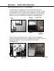
ADJUSTING THE PRODUCT SENSOR POSITION If the label transfer is smooth but is inconsistently applying the label, the product sensor needs to be adjusted. If the label dispenses too late, it will miss the container. (See Fig.20) If it dispenses too soon, the label will fold at the leading edge. (See Fig.20a) Container Container Leading Edge Fold Fig.20 Label Missed Fig.20a If the label dispenses too late and misses the container, move the product sensor towards the entrance end of the conveyor.
ADJUSTING THE LABEL HEIGHT OF THE L-15 Run one test container. Look at the label placement in reference to the height. If the label is too high, turn the applicator height adjust crank handle clockwise to lower the unit. If the label is too low, turn the crank handle counter clockwise to raise the unit. (See Fig.22) Applicator Height Adjust Crank Handle Fig.
ADJUSTING LABEL SKEW If the label is skewed either up or down, the applicator needs to be readjusted for the skew. To do this, there is a knob under the applicator. Turning the knob clockwise will cause the applicator to tip forward. This will cause the trailing edge of the label to go up. Turning the knob counter clockwise will cause the applicator to tip backwards. This will cause the trailing edge of the label to go down. (See Fig.24) Applier Mount Knob Fig.
WASTE WEB REMOVAL Rewind Backing Plate Waste Web 1. To remove waste web, turn off the machine, and remove the web retention clip. 2. Tear the web first. 3. While holding the rewind backing plate, turn the whole waste web in the opposite direction and pull.
OPTIONAL LION SENSOR (Clear Labels) Important: • Web must remain in contact with mounting plate. • Label must pass under the sensor indicator • Small labels should be centered under sensor. • When properly setup, the lights will move between WEB and LABEL. The lights in the “X” region should only light briefly during the transition between WEB and LABEL. Basic (Low Gain) Setup (effective for 90% of labels): 1. Adjust SPAN to minimum (four turns counter-clockwise) 2. While moving labels through the sensor.
LION PRECISION LRD6110 UNIVERSAL LABEL SENSOR INSTRUCTION SHEET M015-3380.06 Introduction: The LION PRECISION LRD6110 LABEL REGISTRATION AND DETECTION SYSTEM is an electronic capacitancebased sensor used to monitor label registration and/or count labels. The sensor will output a signal indicating the leading or trailing edge of the label as it passes through the sensor. No Power during connection! Electrical Connections Warnings: Unused wires must be insulated from contact with other objects.
SECTION 4 TROUBLESHOOTING No power to entire system: 1. Is the emergency switch on the control enclosure pulled out? 2. Is the main switch on the control enclosure “On”? 3. Do all switches in the control enclosure have continuity? Check with ohmmeter. 4. Is the main fuse in the control enclosure good? Check with ohmmeter. 5. Is the master control relay in the control enclosure working? When main switch is turned “On”, it should engage. 6. Is power at power cord? Check with ohmmeter.
CONTROL ENCLOSURE LAYOUT Product Spacer Fuse Applicator Fuse Conveyor Fuse Main Fuse Master Control Relay Turning Unit Fuse “A” “B” “A” “A” “B N.O. Contact Marked “A” N.C.
TROUBLESHOOTING CONTINUED PROBLEM WITH WRINKLE OR SKEWED LABEL The turning unit must be adjusted properly to the top of the conveyor. If the turning unit is tilted up, the container will want to rise up off the conveyor, which will wrinkle the label. Same problem, if the turning unit is tilted to far down it will wrinkle the label or cause the label to be skewed. (See Fig.8a) The backing plate must be adjusted properly. Too much pressure will squish the bottle and cause wrinkles.
TROUBLESHOOTING CONTINUED LABEL DISPENSING FROM APPLICATOR CONSTANTLY Make sure that the label web going threw the label sensor. Make sure that the label sensor is plugged into the applicator. Check the label sensor to see if it is working. Make sure that product sensor is not seeing the trailing edge of the label as it goes by. Try re-setting label sensor. (See Fig.16) WASTE WEB NOT WINDING ON REWIND Adjust rewind take-up.
L-15 MAINTENANCE 1. Remove the Top covers of L-15. 2. Apply a small amount of grease to the felt of the Rewind Sprocket Assembly by moving Rewind Sprocket Assembly towards outside of machine 3. Check Chain tension and lightly grease if dry. Chain should deflect 1/8" to 1/4". 4. Check Gears and Sprockets for wear. 5. Clean Drive and Idler Rollers if dirt and label adhesive is present.
RECOMMENDED SPARE PARTS Revised: 12/8/2004 4:30 PM PART # PART DESCRIPTION 200006 SWITCH, DPST ROCKER (MAIN) 200007 SWITCH, SPST ROCKER (MOTOR) 200012 RELAY, 120V 50/60HZ.
SECTION 6 DRAWINGS AND BILL OF MATERIAL R-320 MAIN ASSEMBLY See Drawing R320-I-00C SENSOR BRACKET ASSEMBLY See Drawing SBK-I-06 ADJUSTABLE BACKING PAD ASSEMBLY See Drawing TA-I-40 CONTROL ENCLOSURE ASSEMBLY See Drawing R320-I-11B SWITCHING AND TIMING ASSEMBLY See Drawing CW-I-00 TURNING UNIT ASSEMBLY See Drawing TA-I-00B APPLIER MOUNTING ASSEMBLY See Drawing R320-I-30 CRANK ASSEMBLY See Drawing CPSS-I-40 MA-300 Z-AXIS ADJUST ASSEMBLY See Drawing MA3-I-00 PRODUCT SPACER ASSEMBLY See Drawing PS3-I-
BillR-320 ofMAIN Material ASSEMBLY *R320-I-00C* R320-I-00C MACHINE: R320 ITEM NUM: 01* 02* 03* 04* 05** 06*** 07* 08* 09* 10* 11* PART NUMBER: PART DESCRIPTION: SBK-I-06 ASSEMBLY, SENSOR BRACKET TA-I-40 ASSEMBLY, ADJUSTABLE BACKING PAD R320-I-11B ASSEMBLY, CONTROL ENCLOSURE TA-I-00B ASSEMBLY, TURNING UNIT L-15 SEE L-15 MANUAL SL-1000 SEE SL-1000 MANUAL R320-I-30 ASSEMBLY, APPLIER MOUNTING PS3-I-01 ASSEMBLY, PRODUCT SPACER R320-I-10C ASSEMBLY, CONVEYOR CPSS-I-10A ASSEMBLY, CONVEYOR BASE R320-I-20 ASSEMBLY
Bill of Material SENSOR BRACKET ASSEMBLY *SBK-I-06* SBK-I-06 MACHINE: R320 ITEM NUM: 01 02 03 04 05 06 07 08 09 10 11 PART NUMBER: PART DESCRIPTION: 500084 HANDLE, 3/8 FEMALE RATCHET SBK-036 BOLT, MICROMETER ADJUSTMENT SBK-031 BAR, SENSOR MOUNTING SBK-027 SHAFT, HORIZONTAL ADJUSTING SBK-030 BLOCK, SENSOR 500081 HANDLE, 10-32 MALE RATCHET 500041A TUBE, SENSOR HOLDER SBK-032 BLOCK, FIBER OPTIC MOUNTING SBK-033 SHAFT, HORIZONTAL ADJUSTMENT 500080 HANDLE, 1/4 MALE RATCHET SBK-034 BLOCK, SENSOR MOUNTING F:\A
*TA-I-40* Bill of Material ADJUSTABLE BACKING PAD ASSEMBLY TA-I-40 MACHINE: R320 ITEM NUM: 01 01* 02 02* 03 03* 04 04* 05 05* 06 06* 07 07* 08 08* 09 10 10* 11** 11** 11** 11** 11** 11** 11** 11** 11** 11** 12** 12** 12** 12** 12** 12** 12** 12** 12** 12** 13 14 14* 15 15* 16 16* PART NUMBER: PART DESCRIPTION: 500084 HANDLE, 3/8 FEMALE RATCHET 500084 HANDLE, 3/8 FEMALE RATCHET SS-124-2 ROD, 3/8 THREADED SS-124-2 ROD, 3/8 THREADED CA-036 STANDOFF, RACHET HANDLE CA-036 STANDOFF, RACHET HANDLE TA-245 BLOCK
*TA-I-40* Bill of Material ADJUSTABLE BACKING PAD ASSEMBLY TA-I-40 MACHINE: R320 ITEM NUM: 17 17* 18 PART NUMBER: PART DESCRIPTION: 853014 WASHER, 1/4" .060 THK 1/2 ODFW 853014 WASHER, 1/4" .060 THK 1/2 ODFW 854012 NUT, 1/4-20 ACORN QTY: 2 3 2 * OPTIONAL 24" TURNING UNIT ** PRODUCT SPECIFIC F:\ACCESSORIES\TA\MANUAL\TA-I-40.dwg MSACCESS Y:\databases\BOM2000.
Bill of Material CONTROL ENCLOSURE ASSEMBLY *R320-I-11B* R320-I-11B MACHINE: R320 ITEM NUM: 01 02 03 04 05 06 07 08 09 10 11 12* 13* 14 15 16 17 18 19 20 21 22 23 24 25 26 27 28 29 30 31 32 33* 33** 34 35 36** 37* 37** 38 39 PART NUMBER: PART DESCRIPTION: ES-I-01 ASSEMBLY, E-STOP SW-I-02 ASSEMBLY, ACCESSORIES ON/OFF SWITCH 200012 RELAY, 120V 50/60HZ. 209021 SOCKET, RELAY 200021 STRIP, 8 TERMINAL EURO 40.
Bill of Material CONTROL ENCLOSURE ASSEMBLY *R320-I-11B* R320-I-11B MACHINE: R320 ITEM NUM: PART NUMBER: PART DESCRIPTION: QTY: NOTE: * L-15 VERSION ** SL-1000 VERSION F:\LABELERS\R-320\MANUAL\R320-I-11B.dwg MSACCESS Y:\databases\BOM2000.
Bill of Material SWITCHING AND TIMING ASSEMBLY *CW-I-00* CW-I-00 MACHINE: R320 ITEM NUM: 01 02 03 04 05 06 07 08 09 10 11 12 13 14 15 16 17 18 19 20 21 22 23 24 25 26 27 PART NUMBER: PART DESCRIPTION: 200204 POTENTIOMETER, 5K LINEAR TAPER 200205 KIT, KNOB DIAL 200406 POT, 5K 10-TURN 200192-1 DIAL, 10 TURN POT (H-22-6A) 200216 POT, 5K OHM 3-TURN 200404 POT, 10-TURN 10K 230001 LIGHT, GREEN PILOT (22MM) 230002 LED, REPLACEMENT 200273 BLOCK, N/C CONTACT 200272 BLOCK, N/O CONTACT 200512 SELECTOR, 3-POSITION 2
Bill of Material APPLIER MOUNTING ASSEMBLY *R320-I-30* R320-I-30 MACHINE: R320 ITEM NUM: 01 02 03 04 05 06 07 08 09 10 11 12* 13 14 15 16 17 18 19 20* 21 22 23 24 25 26 27 28 29 30 PART NUMBER: PART DESCRIPTION: SS-112 KNOB, MICROMETER ADJUST>>> MA-110 SCREW, CROSS ADJUST SS-208A ADJUSTER, MICRON 400009 BEARING, 3/8" THRUST 400010 RETAINER, 3/8" HARDENED BRNG.
Bill CRANK of Material ASSEMBLY *CPSS-I-40* CPSS-I-40 MACHINE: R320 ITEM NUM: 01 02 03 04 05 06 PART NUMBER: PART DESCRIPTION: 810070 PIN, 3/16 X 1-1/2 ROLL 750120B WHEEL, 6" ADJUSTING 400012 BEARING, 1/2" THRUST S84-008-1 BLOCK, TOP CRANK SUPPORT CPSS-022 ROD, 3/4" X 27" ACME ADJUSTER S84-007-1 BLOCK, ADJUSTING F:\ACCESSORIES\CPSS\MANUAL\CPSS-I-40.dwg QTY: 1 1 2 1 1 1 MSACCESS Y:\databases\BOM2000.
Bill of Material MA-300 Z-AXIS ADJUST ASSEMBLY *MA3-I-00* MA3-I-00 MACHINE: R320 ITEM NUM: 01 01 03 04 05 06 06 08 09 PART NUMBER: PART DESCRIPTION: 854003 NUT, 3/8-16 SELF-LOCKING NYLON 400009 BEARING, 3/8" THRUST 850058 SCREW, 5/16-18 X 2" L SHCS 400010 RETAINER, 3/8" HARDENED BRNG. SS-110 BLOCK, MICROMETER ADJ. SS-111 BOLT, MICROMETER ADJ. SS-109 PLATE,MICROMETER ADJ. 800400 OBS. USE 854030 SS-112 KNOB, MICROMETER ADJUST>>> F:\ACCESSORIES\MA-300\MA3-I-00.
Bill of Material PRODUCT SPACER ASSEMBLY *PS3-I-01* PS3-I-01 MACHINE: R320 ITEM NUM: 01 02 03 04* 04** 05* 05** 06 07 08 08*** 09 10 11 12 13 14 PART NUMBER: PART DESCRIPTION: 500085A HANDLE, 3/8 MALE RATCHET PS-3040 GUIDE, SLIDE PS-3007 COVER, PRODUCT SPACER PS-3039 BELT, SPACER 1/2" PS-3039A BELT, SPACER 1-1/8" PS-3038 WHEEL, PRODUCT SPACER 1/2" PS-3038A WHEEL, PRODUCT SPACER 1-1/2" PS-3037 HUB, WHEEL PS-3036 PLATE, BASE 300138 MOTOR, 1/30HP 11 RPM 300139 MOTOR, 1/30HP 50 RPM PS-3035 BAR, MAIN SLIDE PS
BillCONVEYOR of Material ASSEMBLY *R320-I-10C* R320-I-10C MACHINE: R320 ITEM NUM: 01** 01*** 01**** 02** 02*** 02**** 03** 03*** 03**** 04** 04*** 04**** 05 05* 06 07 08 09 10 11 12** 12*** 12**** 13 14** 14*** 14**** 15** 15*** 15**** 16 17** 17*** 17**** 18** 19** 20** 21 22 23 24** 24*** 24**** 25** 25*** 25**** PART NUMBER: PART DESCRIPTION: CA-012 SHAFT, 7" EXTENTION CA-012 SHAFT, 7" EXTENTION CA-012 SHAFT, 7" EXTENTION 500035 PLATE, BACKING 500035 PLATE, BACKING 500035 PLATE, BACKING 500030 CLIP, P
BillCONVEYOR of Material ASSEMBLY *R320-I-10C* R320-I-10C MACHINE: R320 ITEM NUM: 26 27 28 29** 29*** 29**** 30 31 32** 32*** 32**** 33 34 35 35***** 36 37** 37*** 37**** 38** 38*** 38**** 39** 39*** 39**** 40** 40*** 40**** 41** 41*** 41**** PART NUMBER: PART DESCRIPTION: CP2-008 BAR, LOWER TIE CA-06-000-001 BAR, 6" LOWER TIE CP-039 STRIP, MATTOP WEAR CAC-006A FRAMES, 6 FT. CONVEYOR SIDE CAC-008A FRAMES, 8 FT. CONVEYOR SIDE CAC-010A FRAMES. 10 FT.
Bill of Material JUNCTION BOX ASSEMBLY *R320-I-20* R320-I-20 MACHINE: R320 ITEM NUM: 01 02 03 04 05 06* 07** 08** 09 10 11 12 PART NUMBER: PART DESCRIPTION: 100192 CONNECTOR, STRAIGHT 100612-1-CCCC BOX, JUNCTION 200280 RECEPTACLE, FEMALE 4-PIN 200279 CONNECTOR, MALE 4-PIN 100191 CONNECTOR, 90 DEGREE ELBOW UPA-307 COVER, RECEPTACLE 200275 RECEPTACLE, FEMALE 3-PIN 200274 CONNECTOR, MALE 3-PIN 200283 CONNECTOR, MALE 6-PIN 200284 RECEPTACLE, FEMALE 6-PIN 700070B SEAL, 7/8" DIA.
*CPSS-I-10A* Bill of Material CONVEYOR BASE ASSEMBLY CPSS-I-10A MACHINE: R320 ITEM NUM: 01 (A) 01 (B) 02 (C)(32) 02 (C)(34) 02 (C)(36) 02 (C)(38) 02 (C)(40) 02 (C)(42) 02 (C)(44) 02 (D)(32) 02 (D)(34) 02 (D)(36) 02 (D)(38) 02 (D)(40) 02 (D)(42) 02 (D)(44) 03 04 05 06 07 08 (A) 08 (B) 09 PART NUMBER: PART DESCRIPTION: CPSS-026 SHAFT, SPACER CPSS-026B SHAFT, SPACER CPSS-027B-32 ASSEMBLY, 6'-8' CONVEYOR STAND CPSS-027B-34 ASSEMBLY, 6'-8' CONVEYOR STAND CPSS-027B-36 ASSEMBLY, 6'-8' CONVEYOR STAND CPSS-027B-
POWER MODULE SETUP SHEET PLEASE READ CAREFULLY BEFORE INSTALLING SWITCH #1 DELAY SELECT OFF - NO DELAY ON - START AND STOP DELAY SET BY FRONT PANEL CONTROLS START CONTROL - 0 TO 1 SEC. STOP CONTROL - 0 TO 0.1 OR 1.0 SEC.
TECHNICAL SUPPORT When calling for Technical Support: have your Model #: R320 and Serial Number ready: R320 (located on the side opposite the conveyor drive motor cover). L15 (located on the side opposite the roll of labels). Email: fjones@universal1.com Web Site: http://www.universal1.