MODEL 5100-02-IT IT Series COMBUSTIBLE GAS SENSOR MODULE Version 2.00a APPLICABILITY & EFFECTIVITY Effective for all Model 5100-02-IT Modules manufactured after February 15, 2008. Instruction Manual Part Number T12019 Rev.
Model 5100-02-IT Combustible Gas Sensor Module FM APPROVAL ONLY THE FOLLOWING ITEMS, FUNCTIONS AND OPTIONS ARE FM* APPROVED Model 5100-02-IT Combustible Gas Sensor Module Sensor Module Model 5100-02-IT Combustible Gas Sensor Module Model 5100-02-IT-SS Combustible Gas Sensor Module, 316SS Calibration Equipment Model 1200-26 Calibration Gas Delivery System Model 1290-02 Combustible Gas Cylinder Model 5358-01 Calibration Head, Standard Model 5360-00 Calibration Gas Delivery Fitting Model 1260-02
Model 5100-02-IT Combustible Gas Sensor Module TABLE OF CONTENTS 1. PRODUCT DESCRIPTION .............................................................................................................................3 1.1 GENERAL........................................................................................................................................................3 1.2 PRODUCT CONFIGURATION........................................................................................................
Model 5100-02-IT Combustible Gas Sensor Module 6.2 6.3 6.4 6.5 ENCLOSURE REPLACEMENT ....................................................................................................................23 TRANSMITTER REPLACEMENT .................................................................................................................24 SENSOR REPLACEMENT............................................................................................................................
Model 5100-02-IT Combustible Gas Sensor Module 1. PRODUCT DESCRIPTION 1.1 GENERAL The Model 5100-02-IT Catalytic Bead Combustible Gas Sensor Module is a member of the Sentry Information Technology ”IT” family of gas sensor transmitter modules.
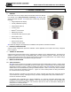
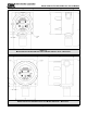
Model 5100-02-IT Combustible Gas Sensor Module Figure 1-1 Model 5100-02-IT Combustible Gas Sensor Module Stainless Steel – Dimensions Figure 1-2 Model 5100-02-IT Combustible Gas Sensor Module Aluminum – Dimensions Page: 4
Model 5100-02-IT Combustible Gas Sensor Module 1.4.2 MODBUS OPERATION All IT gas sensor modules have a Modbus RTU RS-485 serial interface to allow direct connection to any standard PLC or DCS. The Module Address Switch (section 3.5) allows the user to select Modbus addresses 1 thru 15. Switch position “0” allows the user to set addresses up to 254 using the s Menu (See Table 4-3). Figure 3-4 provides the wiring terminations for Modbus connections. 1.4.
Model 5100-02-IT Combustible Gas Sensor Module 1.6 INTERCONNECT WIRING Not supplied with the sensor module, but necessary to the installation and operation is the multi conductor wiring which connects the module to its power source and controller. Before this wiring is installed it is important to read and understand the control system installation instructions to determine wiring requirements and alternatives. 1.7 POWER REQUIREMENTS IT modules operate on DC power between 10 VDC and 30 VDC.
Model 5100-02-IT Combustible Gas Sensor Module 2. CAUTIONS & WARNINGS 2.1 INTRODUCTION Although IT Transmitter Modules are designed and constructed for installation and operation in industrial applications including "hostile" environments, caution should be taken to insure that the installation is made in compliance with this instruction manual and that certain procedures and conditions are avoided. This chapter discusses the necessary cautions.
Model 5100-02-IT Combustible Gas Sensor Module 2.3.1 CATALYTIC BEAD SENSOR MODULES Model 5100-02-IT Gas Sensor Modules are FM performance approved for detection of Combustible gas (methane and hydrogen). The sensor is cross sensitive to the combustible gases indicated in Table 2-1. Risk management planning should take into consideration the potential for the presence of other gases in the monitored area.
Model 5100-02-IT Combustible Gas Sensor Module 3. INSTALLATION NOTE All IT modules are factory pre-configured and calibrated. All modules are tagged to indicate the configuration including the sensor module number. Identify all components during unpacking and install using the factory configuration. 3.1 SENSOR MODULE LOCATIONS Select locations for each sensor module based on the following: 3.2 • Modules should be placed close to the potential source of gas.
Model 5100-02-IT Combustible Gas Sensor Module 3.3 ENCLOSURE INSTALLATION To protect the transmitter and sensor assembly they should be removed from the enclosure and preserved until final installation and wiring termination. Prior to installation and wiring. 1. Remove the transmitter from the module housing by: • Unscrew the two captive panel screws on the face plate. • Lift the transmitter out of the housing. • Unplug the sensor cable from transmitter connector J2.
Model 5100-02-IT Combustible Gas Sensor Module 6. Carefully return the transmitter to the enclosure installing it over the two standoffs. Tighten the retaining screws into the standoffs.
Model 5100-02-IT Combustible Gas Sensor Module 3.5 INSTALLATION CONFIGURATION Table 3-3 and Figures 3-1 through 3-4 provide location and installation details.
Model 5100-02-IT Combustible Gas Sensor Module Figure 3-3 4-20 mA Connection Page: 13
Model 5100-02-IT Combustible Gas Sensor Module Figure 3-4 Digital Interface Connections Figure 3-5 Remote Alarm Reset Page: 14
Model 5100-02-IT Combustible Gas Sensor Module 4. INTRODUCTION – HUMAN-MACHINE INTERFACE SYSTEM The Combustible Gas Sensor utilizes a visual menu system operated by means of a magnet. A magnet stick is supplied for this purpose. The menu system is used to configure alarm set-points, calibrate the sensor module, and for maintenance procedures and alarms acknowledge. 4.
Model 5100-02-IT Combustible Gas Sensor Module 4.2 MAIN MENU Table 4-1 describes the primary human-machine interface operation. Key Function M S M S M S M S E T E T E T E T Description Mode Switch [M] Enter Switch [E] Up Mode Switch [▼] Next Menu 5100-02 First screen at power up-model VX.Xxx Second screen at power up-version Warm.
Model 5100-02-IT Combustible Gas Sensor Module 4.3 CONFIGURE SET-POINTS The sensor module set-points menu is used to initially set-up the alarm set points, relay actions, gas type and range, 4-20 mA action and RS-485/Sentry address and baud rates (See Menu Key in Appendix J). • Alarm Set-points: Once the Set-up menu is selected, press [E] to activate the Alarm Set-point screen. Use the [▲] or [▼] keys to select Low Alarm or High Alarm menu.
Model 5100-02-IT Combustible Gas Sensor Module Key Function Display --0%LEL- M S M S M S M S M S M S M S M S E T E T E T E T E T E T E T E T M S M S E T E T M S M S E T E T Description Reference Default Display Mode ALMRSET: Mode Function - Alarm Reset Mode CALIB:-- Mode SETUP:--- Enter Alarms S.P. Function - Alarm Adjust * A Below Down Relays S.P. Function - Relays Adjust * B Below Down GasFactr S.P. Function - Gas Factor Adjust * C pg. 19 Down 4-20mA S.P.
Model 5100-02-IT Combustible Gas Sensor Module Gas Factor Example M E S T M E S T M E S T Enter GasFactr S.P. Function - Gas Factor Adjust Enter Factr100 Select [E] to select or S or T to adjust factor number and press [E] Enter ACK Acknowledgement of new Gas Factor Value *C 4-20 mA Adjustment Example M S M S M S M S M S M S M S E T E T E T E T E T E T E T Enter Calib S.P.
Model 5100-02-IT Combustible Gas Sensor Module 4.4 MAINTENANCE FUNCTIONS The maintenance menu allows the operator to monitor certain Sensor values, and select the required analog or digital communication interface. The maintenance menu operation is described in Table 4-4.
Model 5100-02-IT Combustible Gas Sensor Module 5. CALIBRATION 5.1 CALIBRATION FREQUENCY The manufacturer specifies that sensor modules must be calibrated every 180 days. Periodic functional tests are advisable for critical applications and hostile environments. The sensor module microprocessor software includes high level self checking algorithms which provide continuous sensor diagnostic and self adjustment.
Model 5100-02-IT Combustible Gas Sensor Module Key Function Display 0%LEL M S M S M S E T E T E T Mode ALMRSET: Mode CALIB: Enter CAL-0% Description Reference Default Display Mode Function - Alarms Reset Mode Function - Calibrate or Sub Routine A Banner: Apply zero gas, enter when done Operation: Confirm area clear of gas, or apply zero air to sensor.
Model 5100-02-IT Combustible Gas Sensor Module 6. SERVICE 6.1 SENSOR MODULE CONFIGURATION The gas sensor module is comprised of the following sub-assemblies (Figure 6-1): 5100-02-IT Gas Sensor Module SPL21810 Alluminum Enclosure (SPL32178 316SS Enclosure) SPL21813 Transmitter Assembly 5200-02 Sensor Assembly There are no field serviceable components below the sub assembly level. 6.
Model 5100-02-IT Combustible Gas Sensor Module 6.3 TRANSMITTER REPLACEMENT The transmitter assembly should be replaced when it is determined that it is unreliable, noisy or cannot be calibrated. This may occur due to age, corrosion or failed components. To replace the transmitter assembly: a. Remove the cover of the main enclosure b. Unscrew the two thumb screws in the top of the cover plate, lift the assembly and rotate 90o to relieve the wiring service loop c.
Model 5100-02-IT Combustible Gas Sensor Module • Wiring terminations clean and correct. 6.5.4 MOISTURE TRAPS AND RAINSHIELDS • Conduit seals and drains installed to avoid moisture build up in electronics enclosure. Water accumulation in sensor module enclosures is a major cause of damage and system failures - take precautions to seal electrical conduits and provide moisture traps and drains to avoid water damage • Rain-shields installed where applicable. 6.5.
Model 5100-02-IT Combustible Gas Sensor Module 7. APPENDICES 7.1 APPENDIX A: SPECIFICATIONS Specifications: Sensor: Type: Range: Repeatability: Response time: Accuracy: Sensor Life: Catalytic Bead 0-100% LEL Combustible +/-1% LEL < 12 sec to 60% full scale +/- 1% for 0-50% LEL range +/- 2% for 51-100% LEL range Typically >3 years Output: Display: Relays (Standard): RS485: Fixed and Scrolling LED High Alarm, Low Alarm, Trouble (SPDT Form C, 0.
Model 5100-02-IT Combustible Gas Sensor Module 7.
Model 5100-02-IT Combustible Gas Sensor Module 7.3 APPENDIX C: LIMITED WARRANTY SIERRA MONITOR CORPORATION warrants its products to be free from defects in workmanship or material under normal use and service for two years after date of shipment. SMC will repair or replace without charge any equipment found to be defective during the warranty period. Final determination of the nature and responsibility for defective or damaged equipment will be made by SMC personnel.
Model 5100-02-IT Combustible Gas Sensor Module 7.
Model 5100-02-IT Combustible Gas Sensor Module 7.
Model 5100-02-IT Combustible Gas Sensor Module 7.
Model 5100-02-IT Combustible Gas Sensor Module 7.
Model 5100-02-IT Combustible Gas Sensor Module Page: 33
Model 5100-02-IT Combustible Gas Sensor Module 7.
Model 5100-02-IT Combustible Gas Sensor Module 7.
Model 5100-02-IT Combustible Gas Sensor Module 7.10 APPENDIX J: Menu Key for 5100-02-IT Gas Sensor Module • Key M : MODE • Key E : ENTER • Key ▲ UP (+) • Key ▼ DOWN (-) MAIN MENU Use the M key to access each of the 4 main sections of the menu.
Model 5100-02-IT Combustible Gas Sensor Module SETUP MENU Once in the SETUP menu use the ▲ or ▼ keys to access each of the 5 main sections of the SETUP menu. ▼ | |- Alarms: ▼ | |- Relays: ▼ | |- GasFactr: ▼ | |- 4-20mA: ▼ | |- RS-485 SETUP: | E – Alarms (Alarms Set-Point Adjustment) | | | E – H.Alarm (High Alarm Setup) | | | E --------------------------- OR---------------------------------------▼ | | | | |- HASP: 60 (Current Hi Alarm set-point |- L.
Model 5100-02-IT Combustible Gas Sensor Module | |----▼ 4-20mA (Verifies 4mA or 20mA output and selects condition of output during calibration) | | | ▼ -------or--------------- E Calib | | | | | |- Out: 4mA | | | | | ▼ --or—E (To calibrate analog output 4mA, |▲ or ▼ to adjust level, | | | then E t o accept) | | |- Out: 20mA | | ▼ --or--E (To calibrate analog output 20mA, |▲ or ▼ to adjust level, | | | then E to accept) | | |- In: 4mA | | ▼ --or—E (To calibrate analog input 4mA, |▲ or ▼ to adjust level, | |
Model 5100-02-IT Combustible Gas Sensor Module THIS PAGE INTENTIONALLY LEFT BLANK Page: 39