OLYMPIC HEAVY DUTY ADJUSTABLE BENCH (OHDADJ) ASSEMBLY INSTRUCTIONS Part # 7627001 Rev.
PARTS LIST KEY 1 2 3 4 5 6 7 8 9 10 11 12 13 14 15 QTY PART # DESCRIPTION 1 LEA7595201 UPPER BENCH FRAME 1 LEA7603101 BACK PAD SUPPORT LEA7605301 ADJUSTABLE SEAT SUPPORT 1 1 LEA7605401 GUIDE ROD 1 LEA7603401 LOWER BENCH FRAME 1 LEA7605501 BENCH ADJUST ANGLE 1 LEA7603901 REAR BENCH SUPPORT 1 LEA7604401 FRONT BENCH SUPPORT 1 LEA7604801 BACK PAD ADJUST 1 LEA73519XX SEAT PAD 1 LEA73540XX BACK PAD 1 LEA7605701 SPRING PIN ASSEMBLY 4 LEA7656301 2” OD WHEEL LEA3238304 M10 X 35mm FLAT HEAD BOLT 2 4 LEA3247904 M10 X
23 1/2” INT TOOTH LOCK WASHER 14 M10 X 35mm FLAT HEAD BOLT 24 3/8” INT TOOTH LOCK WASHER 15 M10 X 35mm BOLT 26 1/2” LOCK NUT 16 3/8 X 2” BOLT 17 3/8 X 2-1/4” BOLT 25 1/2” PLASTIC DOME WASHER 18 1/2 X 1” BOLT 19 1/2 X 3-1/4” BOLT 28 2” OD RUBBER WASHER 20 1/2 X 4-1/2” BOLT 27 3/8” LOCK NUT 21 1/2 X 5” BOLT 22 1/2 X 10” BOLT 3
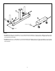
FIGURE 1 REMOVE TAPE FROM BOTH ENDS OF THE HOUSING 4 1 28 29 5 STEP 1: • Insert the GUIDE ROD (4) thru the SHAFT COLLAR and one 2” OD RUBBER WASHER (28) on the LOWER BENCH FRAME (5)as shown in FIGURE 1. • CAREFULLY slide the GUIDE ROD (4) through the HOUSING on the UPPER BENCH FRAME (1). (NOTE: Allow the GUIDE ROD (4) to push the plastic tube out of the end of the HOUSING.) See FIGURE 1.
FIGURE 2 7 27 13 8 24 3/8 X 2-1/4” 17 16 3/8 X 2” STEP 2: • SECURELY assemble two 2” OD WHEELS (13) to the REAR BENCH SUPPORT (7) using two 3/8 X 2” BOLTS (16), four 3/8” INT TOOTH LOCK WASHERS (24) and two 3/8” LOCK NUTS (27) as shown in FIGURE 2. (NOTE: Do not over tighten this connection, wheels should rotate smoothly.
FIGURE 3 26 25 7 23 19 1/2 X 3-1/4” 5 1 1/2 X 3-1/4” 19 8 STEP 3: • SECURELY assemble the REAR BENCH SUPPORT (7) to the LOWER BENCH FRAME (5) using two 1/2 X 3-1/4” BOLTS (19), two 1/2” INT TOOTH LOCK WASHERS (23), two 1/2” PLASTIC DOME WASHERS (25) and two 1/2” LOCK NUTS (26) as shown in FIGURE 3.
FIGURE 4 1/2 X 1” 18 23 6 5 STEP 4: • SECURELY assemble the BENCH ADJUST ANGLE (6) to the LOWER BENCH FRAME (5) using two 1/2 X 1” BOLTS (18) and two 1/2” INT TOOTH LOCK WASHERS (23) as shown in FIGURE 4 FIGURE 5 10 3 24 M10 X 35mm 15 STEP 5: • SECURELY assemble the SEAT PAD (10) to the ADJUSTABLE SEAT SUPORT (3) using two M10 X 35mm BOLTS (15) and two 3/8” INT TOOTH LOCK WASHERS (24) as shown in FIGURE 5 7
FIGURE 6 26 3 1 23 12 1/2 X 5” 21 STEP 6: • SECURELY assemble the ADJUSTABLE SEAT SUPPORT (3) to the UPPER BENCH FRAME (1) using one 1/2 X 5” BOLT (21), two 1/2 INT TOOTH LOCK WASHERS (23), and one 1/2” LOCK NUT (26) as shown in FIGURE 6. • Assemble one SPRING PIN ASSEMBLY (12) to the UPPER BENCH FRAME (1) as shown in FIGURE 6. (NOTE: Tighten jam nut SECURELY.
FIGURE 8 2 26 1 23 1/2 X 4-1/2” 20 STEP 8: • SECURELY assemble the BACK PAD SUPPORT (2) to the UPPER BENCH FRAME (1) using one 1/2 X 4-1/2” BOLT (20), two 1/2 INT TOOTH LOCK WASHERS (23) and one 1/2” LOCK NUT (26) as shown in FIGURE 8. FIGURE 9 26 SERIAL NUMBER 2 23 1/2 X 10” 22 9 STEP 9: • Assemble the BACK PAD ADJUST (9) to the BACK PAD SUPPORT (2) using one 1/2 X 10” BOLT (22), two 1/2 INT TOOTH LOCK WASHERS (23) and one 1/2” LOCK NUT (26) as shown in FIGURE 9.
CAUTION-PLEASE READ There is a risk assumed by individuals who use this type of equipment. To minimize risk, please follow these rules: 1. Inspect equipment daily. Tighten all loose connections and replace worn parts immediately. Failure to do so may result in serious injury. 2. Do not allow minors or children to play on or around this equipment. 3. Exercise with care to avoid injury. 4. Consult your physician before beginning any exercise program.