Network Cameras User Manual Manual Version:2.
Thank you for purchasing our product. If there are any questions, or requests, please do not hesitate to contact the dealer. Copyright Copyright 2015-2018 Zhejiang Uniview Technologies Co., Ltd. All rights reserved. No part of this manual may be copied, reproduced, translated, or distributed in any form or by any means without prior consent in writing from our company. Trademark Acknowledgement and other Uniview's trademarks and logos are the property of Zhejiang Uniview Technologies Co., Ltd.
Environmental Protection This product has been designed to comply with the requirements on environmental protection. For the proper storage, use and disposal of this product, national laws and regulations must be observed. Symbols The symbols in the following table may be found in this manual. Carefully follow the instructions indicated by the symbols to avoid hazardous situations and use the product properly.
Contents 1 Network Connection ·························································································································1 2 Login ··················································································································································1 Preparation ················································································································································1 Logging In to the Web Interface ·············
Configuring Tampering Alarm ··········································································································48 Configuring Audio Detection Alarm ·································································································49 Configuring Alarm Input ···················································································································51 Configuring Alarm Output ··········································································
1 Network Connection Before accessing a network camera (also known as IP Camera or IPC) from a PC, you need to connect the network camera to the PC directly with a network cable or via a switch or router. Network cable IPC PC Use a Shielded Twisted Pair (STP) cable to connect the network interfaces of the network camera and the PC. Network cable IPC Network cable Switch or Router PC Use Shielded Twisted Pair (STP) cables to connect the network interfaces of the camera and the switch or router.
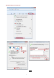
Add the IP address as a trusted site 1 2 1.
NOTE! The IP address 192.168.1.13 in this example is the default IP address. Please replace it with the actual address of your camera if it has been changed. (Optional) Modify user access control settings Before you access the camera, follow the steps to set User Account Control Settings to Never notify. 2 3 4 1 Logging In to the Web Interface The default static IP address of the camera is 192.168.1.13, and the default subnet mask is 255.255.255.0. DHCP is turned on by default.
3. Enter the username and password, and then click Login. For the first login, use the default username “admin” and password “123456”. If you log in with Live View selected, live video will be displayed when you are logged in. Otherwise, you need to start live video manually in the live view window. If you log in with Save Password selected, you do not need to enter the password each time when you log in. To ensure security, you are not advised to select Save Password.
Item Description 3. Set the system time. 4. (Optional) server. 5. (Optional) Set the server for storing photos. Set the server for storing photos based on the actual networking. 6. Set OSD. Set the information displayed on the screen as needed, for example, time. 7. (Optional) Manage users. Change the default password and add common users as needed. Set the Set the system time based on the actual situation. management Set the management server based on the actual networking.
2. Modify the settings as required. The following table describes some major parameters. Parameter Intelligent Mark Untriggered Target Description When enabled, the camera will display an on-screen mark on the target (e.g., face when face detection is enabled) and track it. Video Processing Mode Protocol Set the protocol used to transmit media streams to be decoded by the PC. Recording Record and Snapshot 3.
Network Configuration Ethernet Modify communication settings such as the IP address for the camera so that the camera can communicate with other devices. NOTE! After you have changed the IP address, you need to use the new IP address to log in. The configurations of DNS (Domain Name System) server are applicable when the device is accessed by domain name. Static Address 1. Click Setup > Network > Network. 2. Select Static from the Obtain IP Address drop-down list. 3.
2. Select PPPoE from the Obtain IP Address drop-down list. 3. Enter the username and password provided by your internet Service Provider (ISP). 4. Click Save. DHCP The Dynamic Host Configuration Protocol (DHCP) is enabled by default when the camera is delivered. If a DHCP server is deployed in the network, the camera can automatically obtain an IP address from the DHCP server. To manually configure DHCP, follow the steps below: 1. Click Setup > Network > Network. 2.
2. By default the IPv6 mode is set to Manual. 3. Enter the IPv6 address, set the prefix length and default gateway. The IP address must be unique on the network. 4. Click Save. Wi-Fi NOTE! This function is not supported by some models, please see the actual model for details. 1. Click Setup > Network > Network. Click the Wi-Fi tab. 2. Select Sniffer. 3. Click Save. Some devices can search for Wi-Fi networks and connect. 1. Select Setup > Network > Network. Select Wi-Fi for Wi-Fi Mode. 2.
5. When Wi-Fi Mode is set to Wi-Fi Hotspot, the camera can function as a Wi-Fi hotspot for other devices. 6. Click Save. Port NOTE! This function is not supported by some models. Please see the actual model for details. 1. Click Setup > Network > Port. 2. Configure relevant port numbers. 3. Click Save. FTP All snapshots (except face detection) are saved through the general FTP service.
2. Set the IP address and port for the FTP server, username and password used to upload images to the FTP server, select Upload Images, Overwrite Storage and set Overwrite At (threshold for overwriting images). Some camera models support FTP test. You may test FTP after completing FTP settings correctly. 3. Set the path for saving snapshots on the FTP server and the file name format. For example, set path as Preset No.\\IP Address\\Date\\Hour(s), and set file name as Preset No.
2. Set the IP address and port of the FTP server, username and password used to upload images to the FTP server. 3. Set the path for saving snapshots on the FTP server and the file name format. For example, set path as Preset No.\\IP Address\\Date, and set file name as Preset No.-PTZ Latitude-PTZ Longitude-PTZ Zoom.jpg. 4. Click Save. E-Mail After the configuration of E-mail, when alarms are triggered, you will be able to send messages to the specified E-mail address. 1.
2. Configure relevant parameters of the sender and the recipient. Some camera models support Email test. You may test email after setting the recipient address. The following table describes some major parameters. Parameter Description When enabled, the e-mail will be encrypted using TLS (Transport Layer Security) or Secure Socket Layer (SSL) to protect privacy. TLS/SSL First it tries to send through an SSL connection.
2. Enable Port Mapping and select mapping type. If Manual is selected, then external ports must be configured (external IP is obtained automatically by the camera). If the configured port is occupied, then the Status will show Inactive. 3. Click Save. DNS 1. Click Setup > Network > DNS. 2. Set DNS server addresses. 3. Click Save. DDNS NOTE! This function is not supported by some models. Please see the actual model for details. 1. Click Setup > Network > DDNS. 2. Enable DDNS Service. 3.
EZCloud NOTE! This function is not available to all models. Scan the QR code with your mobile phone (iOS or Android) to download the APP. When installed, run the APP to add the camera. Please refer to the online help in the APP for detailed steps. 1. Click Setup > Network > EZCloud. 2. Select On to enable cloud service. 3. Click Save. 802.1x 802.1x provides authentication to devices (e.g., cameras) trying to connect to a network. Only the authenticated devices can connect the network.
Image Configuration Image Adjustment NOTE! The image parameters displayed and value ranges allowed may vary with camera model. For the actual parameters and value ranges of your camera, see the Web interface. You may move the sliders to adjust settings or enter values in the text boxes directly. Clicking Default will restore all the default image settings. Setting the Scene Set image parameters to achieve the desired image effects based on live video in different scenes. Click Setup > Image > Image.
Column Description Common: recommended for outdoor scenes. Indoor: recommended for indoor scenes. High Sensitivity: recommended for low light environment. Highlight Compensation: can suppress strong light such as headlights on roads and spotlight in parks. Recommended for capturing vehicle license plates. WDR: recommeded for scenes with high-contrast lighting, such as window, corridor, front door or other scenes that are bright outside but dim inside. Custom: set a scene name as needed.
Item Description Set the degree of brightness of images. Brightness Low brightness High brightness The amount of a hue contained in a color. Saturation Low saturation High saturation Set the degree of difference between the blackest pixel and the whitest pixel. Contrast Low contrast High contrast Contrast of boundaries of objects in an image. Sharpness Low sharpness High sharpness 2D Noise Reduction Reduce the noise of images. The function may cause image blurring.
Item Description Normal Flip Vertical Flip Horizontal 180° 90° Clockwise 3. 90° Anti-clockwise To restore default settings in this area, click Default. Exposure NOTE! 1. This function may vary with models. Please see actual Web interface for details. The default settings are scene-adaptive. Use default settings unless modification is necessary. Click Setup > Image > Image and then click Exposure.
For some camera models, the page is displayed as follows. 2. Set the parameters as required. The following table describes some major parameters. Parameter Description Select the correct exposure mode to achieve the desired exposure effect. Exposure Mode Automatic: The camera automatically adjusts exposure according to the environment. Custom: The user sets exposure as needed. Indoor 50Hz: Reduce stripes by limiting shutter frequency.
Parameter Description You can set this parameter only when Exposure Mode is not set to Shutter Priority and when Image Stabilizer is disabled. Slowest Shutter Set the slowest shutter speed that the camera can use during exposure. Note: You can set this parameter only when Slow Shutter is set to On. Adjust the compensation value as required to achieve the desired effects. Compensation Note: You can set this parameter only when Exposure Mode is not set to Manual.
Smart Illumination NOTE! This function may vary with models. Please see actual Web interface for details. 1. Click Setup > Image > Image and then click Smart Illumination. 2. Select the correct IR control mode and set the parameters. The following table describes some major parameters. Parameter Description Infrared: The camera uses infrared light illumination. White Light: The camera uses white light illumination.
1. Click Setup > Image > Image and then click Focus. 2. Select the focus mode as required. Parameter Description Focus Mode Scene 3. Auto Focus: The camera focuses automatically according to the current light condition. Manual Focus: Manually adjust camera focus as required. One-Click Focus: The camera is triggered to focus once when rotating, zooming or going to a preset.
Adjust the red offset manually. Red Offset Note: You can set this parameter only when White Balance is set to Fine Tune. Adjust the blue offset manually. Blue Offset 3. Note: You can set this parameter only when White Balance is set to Fine Tune. To restore the default settings, click Default. Advanced Use the defog function to adjust the clarity of images captured in fog or haze conditions. 1. Click Setup > Image > Image and then click Advanced. NOTE! 2.
2. Select an option from the Lighting Type drop-down list. 3. To restore the default settings, click Default. Configuring Iris and Lens Mode NOTE! This function is only supported by certain network box camera types. Please see the actual model for details. Please use the lens with P-Iris control mode, and connect the iris control cable to the Z/F port of the camera. Iris can be set only when Lens Mode is set to P-IRIS. 1. Click Setup > Image > Image and then click Advanced. 2.
The OSD interface of some models is displayed as follows. 2. Select the position and content of the OSD. Position: Click the desired box in the Live View area. After the cursor shape is changed, click and hold the button to move the box to the desired position. To set the position precisely, use the X and Y coordinates under Overlay Area. Overlay OSD Content: The drop-down list provides Time, Preset and Serial Info. You may also select Custom and enter the content you want.
Privacy Mask On certain occasions, you may need to set a mask area on the camera image to protect privacy, for example, the keyboard of an ATM machine. When PTZ changes its position or zooms, the Privacy Mask will be adjusted accordingly to protect the area all along. NOTE! 1. This function may vary with models. Please see the actual Web interface for details. Some models support up to 24 privacy masks. The same picture shows up to only 8 privacy masks. Click Setup > Image > Privacy Mask.
2. Click to add a privacy mask, and click to delete a mask. To mask a position: Click the box (with Mask displayed on it) to activate the mask. After the cursor shape has changed, drag the box to the intended position. To mask an area: Use the mouse to draw a box on the area you want to mask. When privacy mask is configured, the intended area is blocked. The following shows an example.
2. Modify the settings as required. The following table describes some major parameters. Parameter Description Three options: H.265, H.264 and MJPEG. Note: Video Compression Image Quality cannot be set when Video Compression is set to H.265 or H.264. When set to MJPEG, only three frame rates are available: 1, 3 and 5; and Bit Rate, I Frame Interval, Smoothing and U-Code cannot be set. The bit rate changes to the default when you change the setting between H.264 and H.265.
Parameter Description Advanced Mode: The actual bit rate is around 1/2 of the set bit rate. Note: When U-Code is enabled, video compression only supports H.264 and H.265. MJPEG is not supported. When U-Code is enabled, the capture mode does not support frame rates higher than 30. Set the extent of smoothing. Choosing Clear means disabling Smoothing. Moving the slider toward Smooth increases the level of smoothing but will affect image quality.
Parameter Description Input Gain Audio signal amplification for sampling. The greater the gain, the greater amplification. Noise Suppression Used to reduce noise in images. To enable noise suppression, select On. Audio output channel. To enable audio output, select Enable. Channel Note: Only some camera models support two channels. 3. Click Save. Snapshot 1. Click Setup > Video & Audio > Snapshot. 2. Select On, and then set resolution, most large and schedule as needed.
ROI When Region of Interest (ROI) is enabled, the system ensures image quality for ROI first if the bit rate is insufficient. NOTE! This function is not supported by some models. Please see the actual model for details. 1. Click Setup > Video & Audio > ROI. 2. Click , and then drag the mouse to cover the intended part of the images. To delete, select the area and then click . Media Stream Configuration Media Stream You can display the established media streams from a camera.
2. Click , select a stream type, and then set the IP address and port number of the unicast or multicast group for the decoding device that receives audio and video streams from the camera. If you want the device to establish the media stream that has been configured before automatically after the restart, select Yes for Persistent. 3. To delete a stream, click . 4. Click Submit to complete the operations.
2. Set the multicast address (224.0.0.0 to 239.255.255.255) and port number (0 to 65535). 3. Click Save. Intelligent Alarm Configuration You can configure intelligent monitoring to count people and monitor moving objects. Intelligent monitoring includes people counting, intrusion detection, and auto tracking. The supported functions may vary with camera model. Smart Settings Click Setup > Intelligent > Smart Settings.
For some camera models, the page is displayed as follows. Cross Line Detection Cross line detection detects objects that cross a virtual line in live video and triggers alarm when such an event is detected. 1. Click Setup > Intelligent > Smart Settings. Choose Cross Line and then click 35 .
2. Select Cross Line Detection. 3. In the Detection Rule area, click 4. On the small preview window, drag the line to the intended position and set the detection range. 5. Set the direction and sensitivity for the camera to decide whether to report a cross line detection alarm. 6. Set the alarm-triggered actions and arming schedule as required. For the detailed steps, see the descriptions of alarm-triggered actions in Configuring Motion Detection Alarm. 7. Click Save.
2. Select Intrusion Detection. 3. In the Detection Rule area, click 4. Drag the borders of the box to set the intended position and range. 5. Set time threshold, sensitivity, and percentage for the camera to decide whether to report an intrusion detection alarm. Time Threshold: The minimum length of time that the intruder stays in the detection area before an alarm will be reported. Sensitivity: Sensitivity of detection. A greater value means higher detection sensitivity.
2. Select Enable Object Moving Detection. 3. In the Detection Rule area, click 4. Drag the box to set the position and effective range. 5. Set time threshold and sensitivity to decide whether to report an intrusion detection alarm. Time threshold: Minimum duration an object is detected in the specified area to trigger an alarm. Sensitivity: The greater the number, the higher the sensitivity. An alarm is reported if an object is detected in the specified area for the specified length of time.
2. Select Enable Object Left Detection. 3. In the Detection Rule area, click 4. Drag the box to set the position and effective range. 5. Set time threshold and sensitivity to decide whether to report an intrusion detection alarm. Time threshold: Minimum duration an object is detected in the specified area to trigger an alarm. Sensitivity: The greater the number, the higher the sensitivity. An alarm is reported if an object is detected in the specified area for the specified length of time.
2. Drag the borders to set the intended position and range. 3. Set detection parameters according to actual needs. 4. Set the alarm-triggered actions and arming schedule as required. For the detailed steps, see the descriptions of alarm-triggered actions in Configuring Motion Detection Alarm. 5. Click Save. 6. Click Start Intelligent Analysis. People Counting NOTE! 1. Only some camera models support this function. The supported alarm triggering and arming schedule may vary with camera model.
2. Select Enable Passenger Flow Detection. Select a detection mode, set report interval and sensitivity. 3. Click Draw Detection Area, and then draw a detection area on the preview window on the left, e.g., a square. 4. Click Draw Entrance Direction, and then draw the direction on the preview window on the left. The direction is usually vertical or sloping. 5. Set Max. Size and Min. Size under Filter by Object Size.
2. Set tracking timeout (unit: sec) and zoom ratio. 3. Click Save. Heat Map The heat map uses different colors to display visitor traffic patterns. A dark color, red, for example, indicates higher traffic density. 1. Click Setup > Intelligent > Smart Settings. Choose Heat Map and then click . 热力图 2. Select Enable. 3. Set Background Update Rate. The greater the value, the quicker the image refreshes. 4. Set Sensitivity. The greater the value, the more likely that small objects will be detected.
7. Set the alarm-triggered actions and arming schedule as required. For the detailed steps, see the descriptions of alarm-triggered actions in Configuring Motion Detection Alarm. 8. Click Save. Defocus Detection NOTE! Only some camera models support this function. The supported alarm triggering and arming schedule may vary with camera model. Please see the actual Web interface for details. Use defocus detection to detect defocus of the camera and to report an alarm when such an event is detected.
2. Select Scene Change Detection. 3. Set detection sensitivity. Set the alarm-triggered actions and arming schedule as required. For the detailed steps, see the descriptions of alarm-triggered actions in Configuring Motion Detection Alarm. 4. Click Save. Advanced Settings Advanced settings include snapshot clarity and detection mode for intelligent functions. Photo parameters Set clarity of snapshots. 1. Click Setup > Intelligent > Advanced Settings. Click Photo parameters tab. 2.
Detection Parameters NOTE! Only some camera models support advanced settings. Please see the actual Web interface for details. The default detection mode is Normal Mode. Set as required. 1. Click Setup > Intelligent > Advanced Settings. Click Detection parameters tab. 2. Choose a detection mode. Choose Filter Repeated Motion Mode to prevent repeated alarm reporting caused by repeated motion detected in the surveillance environment. 3. Click Save.
2. In the Detection Area area, click to add a new detection area. To delete a detection area, click . 3. Click and drag the mouse to set a detection area. 4. Set the detection sensitivity, object size, and history for the camera to decide whether to report a motion detection alarm. Moving the slider to the right increases detection sensitivity. When the extent of motion within the detection area exceeds the set object size, the camera reports an alarm.
Item Description Select the check box. This setting is the alarm output interface linked to motion detection alarm. Alarm Output 1 Note: When an alarm is reported, the camera triggers alarm output so as to trigger actions by a third-party device. Select the check box and set the preset linked to motion detection alarm. Goto Preset Upload to FTP Note: Make sure you have set presets. Otherwise, you cannot set this parameter. For details about how to set a preset, see Setting Presets.
Drag the mouse to draw a plan Edit time periods in the table Note: Plan drawing using a mouse is only supported by IE versions later than 8.0. After setting the plan for one day, you can apply the same settings to other days by clicking Copy and Paste. 7. Click Save. Grid Detection 1. Click Setup > Events > Motion Detection. Set Detection Mode to Grid. 2. Detection area(s) can be irregular on the grid. 3.
2. Select On for Tampering Alarm. 3. Set detection sensitivity and duration for the camera to decide whether to report a tampering alarm. Sensitivity is divided into three levels: high-level, mid-level and low-level. Compared with mid-level sensitivity, the camera can detect blocking from a farther location when sensitivity is set to high. The camera reports an alarm when the lens is blocked for a specified length of time. Tampering alarm is effective to the whole screen.
2. Select Enable for Audio Detection, select a detection type and set the difference or threshold. To disable audio detection, clear the Enable check box. The following table describes some major parameters. Parameter Description Detection Type Sudden Rise: An alarm is reported when the rise of volume exceeds the difference. Sudden Falls: An alarm is reported when the fall of volume exceeds the difference.
Parameter Description Difference 3. Set the alarm-triggered actions and arming schedule as required. For the detailed steps, see the descriptions of alarm-triggered actions in Configuring Motion Detection Alarm. 4. Click Save. Configuring Alarm Input The camera can receive alarm information from a third-party device. To use this function, you need to configure the following information for alarm input first: port, alarm name, alarm type (normally open or normally closed) and alarm reporting time.
2. Select alarm and set the alarm name. 3. Select N.O. or N.C. according to the type of the third-party alarm input device. For example, if the third-party alarm input device is normally open, you need to select N.O. here, so that the camera can receive alarm information from the third-party alarm input device. 4. Set actions to be triggered by an input alarm and the plan. For the detailed steps, see the descriptions of alarm-triggered actions in Configuring Motion Detection Alarm. 5. Click Save.
CAUTION! Strictly follow the sequence when powering on the devices to avoid damaging camera components: 1. Check that the alarm type is set to Normally Open (default setting), and that the camera and the alarm output device are powered off. 2. After completing the connection, power on the camera first and then power on the alarm output device. Memory Card Storage NOTE! This function is not supported by some models, and may vary with models. Please see the actual model for details.
Data Overwrite Policy Post-Record(s) 3. To format the memory card, disable the storage function for the card first. Then Click Format and then click OK to confirm the operation. The system will restart when the format is completed. Information about the total and free space is displayed. Overwrite: If there is no free space in the memory card, new data will overwrite the existing data repeatedly. Stop: If there is no free space in the memory card, new data will not be saved to the memory card.
2. Select Planned Storage, and then set the periods during which the camera records video to the memory card. 3. Click Save. NOTE! Planned storage is not effective when manual storage and planned storage are both enabled. To query recordings in the memory card, see Video Playback and Download with Edge Storage. Setting Cache Post Recording A camera under centralized management can use the memory card as a backup storage resource of the central management server.
Disable edge storage 1. Click Setup > Storage > Storage. 2. Set Storage Policy to Off. Post-Record is displayed if the camera is capable of this feature and then set Post-Record(s). 3. Click Save. System Maintenance NOTE! This function is not supported by some models. Please see the actual model for details. Security User Management There are two types of users in the system: Administrator: referred to as “admin” in this manual.
NOTE! This function is not supported by some models. Please see the actual model for details. 1. Click Setup > Network > Port. 2. Enter the port number in the HTTPS Port text box. 3. Click Save. 4. Click Setup > Security > Network Security > HTTPS. 5. Select On for HTTPS. You may import a custom SSL certificate as needed. 6. Click Save. Next time you log in, enter the address in https://IP:HTTPS port number format, for example, https://192.168.1.13:443 to enter secure channel mode.
2. Select the check box to enable the ARP binding function and set the gateway MAC address. 3. Click Save. IP Address Filtering Use IP address filtering to allow or forbid access from specified IP address(es). NOTE! This function is not supported by some models. Please see the actual model for details. 1. Click Setup > Security > Network Security > IP Address Filtering. 2. Select On to enable IP address filtering. 3. Select a filtering mode, and then add IP address(es). 4. Click Save.
2. Select On to enable friendly password and MAC Authentication. 3. Click Save. Watermark Use watermark to encrypt custom information with video to prevent unauthorized delete or alteration. NOTE! Only some camera models support this function. 1. Click Setup > Security > Watermark. 2. Select On to enable watermark, and then input watermark content. 3. Click Save. Setting the System Time You can use the following methods to adjust the system time of your device.
3. Click Save. The camera will periodically synchronize time with the NTP server. Setting the DST 1. Click Setup > Common > Time, and then click the DST tab. 2. Select On for DST, set the start time, end time, and DST bias. 3. Click Save. Setting Servers Intelligent Server You need to configure the intelligent server if an ultra sensitive camera is managed by a central server. NOTE! 1. Only some camera models support intelligent server.
2. Select PTZ Control from the Port Mode drop-down list. The following table describes some major parameters. Parameter Description Set the PTZ protocol that the channel supports. PTZ Protocol Note: You can set this parameter only when Port Mode is set to PTZ Control. When PTZ Protocol is set to INTERNAL-PTZ, the camera can connect to the external PTZ without using the serial port (serial port parameters are grayed out).
Transparent channel Use the RS485 serial port to achieve transparent data transmission with the third-party device. Transparent channel is mainly used to achieve transparent data transmission between two devices. NOTE! This function is not supported by some models. Please see the actual model for details. Make sure that you have set Port Mode to Trans-Channel for your camera. 1. Click Setup > System > Ports & Devices, and then click the Serial Port tab. 2.
2. Select OSD from the Port Mode drop-down list. Select Enable OSD Report (so OSD data will be uploaded to the platform). 3. Click Save. ONVIF Transparent Channel Transmit data through the transparent channel (ONVIF) between the camera's RS485 port and a third-party device. 1. Click Setup > System > Ports & Devices, and then click the Serial Port tab. 2. Set Port Mode to Select Trans-Channel via ONVIF. 3. Click Save. Wiper Control Set wiper parameters before you can control the wiper.
2. Set control mode for the wiper. The following table describes some major parameters. Parameter Description Serial Port The wiper is controlled by PELCO-D instructions; therefore, the PTZ protocol should be set to PELCO-D. See PTZ control for details. Alarm Input/Output Use alarm input and output to open or close the circuit and control the wiper. Viewing Device Status You can view the current status of your camera. 1. Click Setup > Common > Basic Info. IPC IPC A V1.0 2102335CC3531740100232 192.
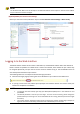
2. Click Refresh to update the storage status. 3. You can export or delete photos in the Image List area. Upgrading the Device If the device is managed by the central management server and you want to upgrade the devices in batch mode, it is recommended to perform the upgrade operation on the central server. For detailed steps, see the user manual for the central management server. 1. Click Setup > System > Maintenance. 2. Under Software Upgrade, click Browse and select the correct upgrade file. 3.
NOTE! You must use the correct upgrade file for you camera. Otherwise, unexpected results may occur. The upgrade file is a ZIP file and must include all the necessary files. The boot program loads the operating system and then the system starts running. The upgrade boot program function is disabled by default, and only the camera will be upgraded to the latest version.
4. To restore default configurations, click Default and then confirm the operation. The device will restart and restore the default configurations. Clicking Default with the check box selected will completely restore the device to factory default settings. Collecting Diagnosis Information Diagnosis information includes logs and system configurations. You can export diagnosis information to your PC. 1. Click Setup > System > Maintenance. 2.
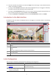
2. Enter the actual height from the installed Infrared Dome to the ground. 3. Click OK. Fisheye Camera Parameter To display video properly, you need to set fisheye parameters properly according to the actual mounting mode. NOTE! This function is only supported by fisheye cameras. Please see the actual model for details. 1. Click Live View > Mount. Select the mounting mode. The selected mounting mode must be consistent with the actual mounting mode.
2. Set the parameters. The following table describes some major parameters. Parameter Description Eleven display modes: Original Image Panoramic Panoramic+3PTZ Panoramic+4PTZ Panoramic+8PTZ 360°Panoramic+1PTZ 180°Panoramic Fisheye+3PTZ Fisheye+4PTZ 360°Panoramic+6PTZ Fisheye+8PTZ Three mounting modes: Ceiling Wall Desktop Note: The selected mounting mode must be consistent with the actual mounting mode.
Live View Toolbar NOTE! The supported live view operations may vary with camera model. For the operations that your camera supports, see the Web interface. Button / Description Play/stop live video. Adjust the output volume for the media player on the PC. Adjust the microphone volume on the PC during audio communication between the PC and the camera. Take a snapshot of the current image displayed on the PC. Note: The path for saving snapshots are set in System Configuration. Start/stop local recording.
Button Description Reset the packet loss rate to zero. Note: After you move the mouse cursor on a live view window, this button appears on the floating toolbar. Display packet loss rate and bit rate information at the bottom of the window. Note: After you move the mouse cursor on a live view window, this button appears on the floating toolbar. Click this button to always display the information.
2. Click and hold the mouse button, and then drag from top down (draw a rectangle) to specify an area. To restore the original image size and zoom in on other areas of the image, right-click the mouse. 3. To exit, click . Using Area Focus NOTE! The supported live view operations may vary with camera model. For the operations that your camera supports, see the Web interface. 1. On the Live View page, click on the toolbar. 2.
3. To exit, click . Using 3D Positioning NOTE! This function is available only for network PTZ cameras and network box cameras equipped with motorized zoom lens and PTZ. Please see actual models for details. 1. On the Live View page, click on the toolbar. 2. Click and hold the mouse button, and then drag from top down (draw a rectangle) to specify an area. Dragging reversely (from down top) will zoom out. 3. To exit, click .
When Panoramic is selected, dewarped panoramic images are displayed as follows.
NOTE! If the ceiling mount or desktop mount is adopted, the panorama image (two 180° images) is a dewarped image of the fisheye preview image (360° image). Please mount the camera with an appropriate angle of view according to the actual surveillance requirements.
5 Video Playback and Download with Edge Storage NOTE! Edge storage refers to recording video to the memory card of a frontend device (mostly a camera). Local recording refers to recording video to a local PC client. Before you play back video with edge storage, check that the camera has been installed with a memory card and storage has been configured. This function is not supported by some models. Please see actual models for details. Video Playback 1. Click Playback on the home page. 2.
6 2. Search for video within a specified period. The results will be shown in a list. 3. Select your video and click Download. The video will be downloaded to your local path from the memory card (local path can be changed in Local Settings). 4. Click Open to show the folder where the downloaded video is saved. PTZ Control This function is available only for the PTZ dome cameras or a box camera installed on a Pan/Tilt motor.
Item Description Adjust camera focus. Adjust camera zoom. Increase or decrease iris diameter. Shortcut keys for PTZ control. After the mouse cursor changes to one of these shapes in live view, click and hold the left mouse button to operate the PTZ camera. Note: Only PTZ dome cameras and PTZ cameras support this function. These buttons are unusable when you are using 3D positioning or digital zoom. Shortcut keys for zooming in or out in live view.
Go to a preset 1. On the Live View page, click Preset on the control panel. 2 1 2. Click for a preset. The PTZ camera goes to the selected preset. Delete a preset 1. On the Live View page, click Preset on the control panel. 2 1 2. Click for a preset and then confirm the delete. Setting Patrol A patrol route is the track by which a PTZ camera follows when moving from a preset to the next. The length of time that a PTZ camera stays at each preset is configurable.
records the route and adds it to the action list. You may select Keep Rotating so the PTZ camera follows the same route and patrols repeatedly. Add a patrol route 1. On the Live View page, click Patrol on the control panel. 2. Click 3. On the Add Patrol page, enter the route ID and name, and then click Add to add a patrol action. Up to 64 actions are allowed. Each line includes two actions when action type is set to Move Direction and Zoom, so 32 actions are allowed.
1 2 2. Click to start recording the patrol route. You can adjust the direction and zoom of the camera during the recording. The system records the motion and track of the camera and adds them to the action list. 3. Click to finish recording. Then the patrol route is saved as a mode route automatically. You can click to start patrol or to delete the mode route. Make a patrol plan 1. On the Live View page, click Patrol on the control panel.
1 2 2. Click . The page for setting patrol plans is displayed. 3. Set the correct patrol time and route. 4. Select Enable Patrol Plan. 5. Click OK. Start a patrol route After you have added a patrol route, select the patrol route to start patrol. 1. On the Live View page, click Patrol on the control panel. 1 2 2. Click for the patrol route you want to start. Edit a patrol route 1. On the Live View page, click Patrol on the control panel.
2 1 2. Click for the patrol route you want to edit and modify the settings as required. Delete a patrol route 1. On the Live View page, click Patrol on the control panel. 2 1 2. Click for the patrol route you want to delete and then confirm the delete. Setting Home Position PTZ camera will return to home position if no operation is made within a specified period. NOTE! 1. This function is available for network PTZ cameras only. You need to add presets or a patrol route first.
2. Select a mode and ID. 3. Click Save. Remote Control PTZ When the third-party platform is used and the PTZ protocol does not match that, you can set the remote control function to control the PTZ. NOTE! This function is only supported by PTZ cameras. 1. Click Setup > PTZ > Remote Control. 2. Select On to enable Remote Control. Set the listener port and address code. The following table describes some major parameters.
4 2 3 1 2. Use directional buttons to rotate the camera to an intended position. 3. Click to set the current position as a limit. For example, click Clicking on the top to set the upper limit. will rotate the camera to the current position if the direction has been changed. 4. Repeat the above steps to set all limits as needed (up, down, left, right). 5. Click Save. 6. Click Start PTZ Limit to apply the setting. 7. Click to delete settings and reset the limit. Resume Patrol 1.
Appendix A Glossary Acronym Description ARP Address Resolution Protocol CBR Constant Bit Rate DNS Domain Name Service DDNS Dynamic Domain Name Service DHCP Dynamic Host Configuration Protocol DST Daylight Saving Time FTP File Transfer Protocol GOP Group Of Pictures GUI Graphical User Interface HTTPS Hyper Text Transfer Protocol over SSL IE Internet Explorer IMOS IP Multimedia Operation System IP Internet Protocol IPC IP Camera MTU Maximum Transmission Unit NTP Network Time P
Appendix B FAQ What to do if no message prompts me to install ActiveX when I log in on a Windows 7 PC the first time Answer: Follow these steps to turn off UAC and then log in again: 1. Click the Start button, and then click Control Panel. 2. In the search box, type uac, and then click Change User Account Control Settings. 3. Move the slider to the Never Notify position, and then click OK. 4. After UAC is turned off, log in again.