
Installation Guide
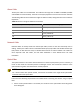
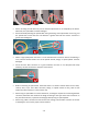
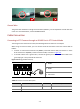
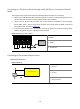
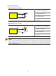
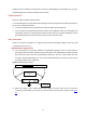
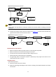
Table Of Contents
- 01-Front Cover.pdf
- 02-Preface.pdf
- 03-Body.pdf
- 1 Overview
- 2 Installation
- Mounting Optical Module
- Wall Mount
- Mounting Accessories
- PTZ Dome Camera
- Mounting bracket
- Mounting dome unit (for cameras with tail cable unit)
- 1. Lead the tail cable through the bracket, and push up.
- 2. Slide the camera holder into the inner track and turn the tail cable unit till it is blocked by the bracket adapter screw. And then tighten the screws.
- 3. Fasten the bracket to the four expansion bolts on the wall with flat washers, spring washers, and nuts.
- 4. Hang one end of the safety rope to the camera and the other to the bracket before mounting the dome.
- 5. Attach the tail cable unit on the hook with the camera perfectly aligned with the three positioning pilot pillars, push the dome camera in place, and then secure the three stainless screws.
- 6. Mount the top sun shield.
- Mounting dome unit (for cameras without tail cable unit)
- Box Camera
- Mounting camera without housing
- Mounting camera with housing
- Bullet Camera
- Locate drill holes
- For camera without bracket
- For camera with bracket
- Fixed Dome Camera
- 1. Locate the positions of the holes.
- 2. Drill holes on the wall.
- 3. Mount plastic rivets of self-tapping screws.
- 4. Mount the dome.
- 5. Adjust the monitoring direction of the lens (tighten screws after vertically adjusting the lens).
- 6. Mount the lining and ensure that it is tightened up.
- 7. Mount the transparent dome housing.
- a. Align the screw holes in the base, and tighten the two cross-recessed pan-head screws on the edge of the transparent dome housing to fix it, as shown by ( in the following figure.
- b. Align the grooves (non-tail cable grooves) of the transparent dome housing to the buckle of the base, and push up the dome housing to fix it, as shown by ( in the following figure.
- Plastic Fixed Dome
- 1. Secure screws to the adapter.
- 2. Attach the adapter to the mounting bracket.
- 3. Secure the camera unit to the adapter and connect the cables.
- 4. Remove the dome bubble.
- 5. Adjust the monitoring direction.
- 6. For manual lens, power on the device, and then turn the rotate knob to get clear image.
- 7. For automatic lens, you can adjust the image directly after power up.
- Pendant Mount
- Mounting Accessories
- PTZ Dome Camera
- Mounting the pendant bracket
- 1. Locate the positions of the holes.
- 2. Select a drill bit matching the outer diameter of the expansion bolt. For the hole depth, refer to the bolt length.
- 3. Knock the expansion bolts, and verify that they are tightened up.
- 4. Screw-in the bracket adapter (G1 ½ male thread) to the connector of the pendant mount bracket.
- 5. Tighten the screws (M4) at the bracket.
- For cameras with tail cable unit
- For cameras without tail cable unit
- Mounting the pendant bracket
- Miniature Camera
- Corner Mount
- Standing Pole Mount
- Pole Mount
- In-Ceiling Mount
- PTZ Dome Camera
- 1. Drill a hole in the ceiling.
- 2. Put the inside bracket through the hole of the ceiling and align the inner edge of the bracket with the edge of the hole.
- 3. Fix the inside bracket and the outside bracket, align two screw holes on the outside bracket to hole positions on the inside bracket, fasten the two screws using a screwdriver, and verify that the inside bracket and the outside bracket have been fi...
- 4. Mount the dome to the adapter bracket.
- 5. Fix one end of the safety rope to a hole on the adapter bracket.
- 6. Mount the dome to the ceiling.
- a. Hang the other end of the safety rope onto the inside bracket on the ceiling as shown by ( in the following figure.
- b. Connect all cables between the ceiling and the tail cable of the dome as shown by ( in the following figure.
- c. Slowly push the adapter bracket carrying the dome upward into the ceiling as shown by ( in the following figure.
- 7. Fasten the adapter bracket and the outside bracket.
- 8. Tighten the locking screws on the adapter bracket by using a screwdriver, so as to fix the adapter bracket and prevent the adapter bracket from falling.
- 9. Attach the plastic panel to the in-ceiling bracket and make sure only the housing is visible from outside.
- Metal Fixed Dome Camera
- 1. Drill holes in the ceiling.
- 2. Mount the inside bracket to the ceiling.
- 3. Fix the ceiling bracket to the in-ceiling bracket.
- 4. Refer to Step 5 to mount the camera to the ceiling bracket.
- 5. Mount the camera to the ceiling and fix the in-ceiling bracket.
- a. Connect all cables between the ceiling and the tail cable of the camera, as shown by ( in the following figure.
- b. Slowly push the in-ceiling bracket holding the camera towards the ceiling, align the screw holes of the inside bracket, and then use a screwdriver to fix the in-ceiling bracket, as shown by ( in the following figure.
- 6. Mount a plastic panel to protect the camera.
- Plastic Fixed Dome Camera
- PTZ Dome Camera
- Ceiling mount
- Mounting Accessories
- Indoor PTZ Dome Camera
- 1. Locate the positions of the holes. Verify that the holes on the wall align with the inner holes of the ceiling bracket.
- 2. Drill holes (depth: about 30 mm) on the wall by using a drill bit of the diameter 6 mm or 6.5 mm.
- 3. Mount the plastic rivets of self-tapping screws, knock the plastic rivets into the guide holes and ensure that they are tightened up.
- 4. Mount the ceiling bracket by fastening the self-tapping screws through the bracket guide holes to the ceiling.
- 5. Mount the dome and the adapter bracket. Align the four screws of the adapter bracket with the mount points of the dome, and tighten the screws by using a screwdriver.
- 6. Fasten one end of the safety rope to the adapter bracket hole.
- 7. Fasten the other end of the safety rope to the ceiling bracket, and connect all cables.
- Fixed Dome Camera
- Analog fixed and mini dome camera
- 1. Locate the positions of the holes.
- 2. Drill holes on the wall.
- 3. Mount the plastic rivets of self-tapping screws.
- 4. Mount the dome.
- 5. Adjust the monitoring direction of the lens (tighten screws after vertically adjusting the lens).
- 6. Attach the lining and lock it with the buckle on the base.
- 7. Mount the transparent dome housing.
- a. Align the screw holes in the base, and tighten the two cross-recessed pan-head screws on the edge of the transparent dome housing to fix it, as shown by ( in the following figure.
- b. Align the grooves (non-tail cable grooves) of the transparent dome housing to the buckle of the base, and push up the dome housing to fix it, as shown by ( in the following figure.
- Metal fixed dome ceiling mount
- 1. Locate the positions of the holes.
- 2. Drill holes on the wall.
- 3. Mount the plastic rivets of self-tapping screws.
- 4. Mount the ceiling bracket.
- 5. Connect all cables, and fix the dome and ceiling bracket.
- 6. Remove the transparent dome housing and adjust the monitoring direction of the lens.
- 7. For a manual zoom lens camera, power on the device and adjust the manual zoom lens to get clear images.
- 8. For a motorized zoom lens camera, it will automatically adjust the lens to present images.
- Plastic fixed dome camera
- 1. Locate holes on the ceiling.
- 2. Drill holes according to drill template.
- 3. Knock in the plugs and make sure they are tightened in place.
- 4. Remove the dome bubble.
- 5. Mount the dome unit and connect the cables.
- 6. Adjust the monitoring direction.
- 7. Connect the power. For a manual lens, adjust the lens until you get a satisfying image.
- 8. Connect the power. For a manual lens, adjust the lens until you get a satisfying image. For a motorized lens, adjust the lens through Web.
- Mini dome camera ceiling mount
- 1. Locate holes on the ceiling.
- 2. Drill holes according to the drill template.
- 3. Knock in the plastic plug.
- 4. Remove the bottom ring.
- 5. Connect the cable and then secure the dome.
- 6. Adjust the monitoring direction.
- 7. Mount the bottom ring.
- 8. The above steps are for concealed installation. For open installation, lead the cables out from the open slots and see Mount the bottom ring. to finish the installation.
- Parking lot detection camera
- Analog fixed and mini dome camera
- Waterproof Components for an RJ-45 Plug
- 3 Cable Connection for External Device
- 4 Lightning Protection and Grounding
- Outdoor Protection Box
- Lightning Protection
- External Protection
- Cable Protection
- Inner Protection
- Requirements for Signal Arrestor
- 1. The connection for the arrestor conforms to equipotential principle. There is a joint point for grounding cables connection between arrestor and device. The cable between arrestor and joint point must be shorter than the recommended value by the ar...
- 2. When the length of the cable between the arrestor and joint point does not meet the connection requirements, you need to connect the device and arrestor as shown in the Figure 4-2.
- 3. Connect the arrestor and the device as shown in the Figure 4-3. Connect the IN terminal with signal channel and OUT terminal with the device.
- Requirements for Power Arresor
- Installing Arrestor
- 1. Place the arrestor close to the device.
- 2. Adjust the grounding cable length on the arrestor according to the distance between the device and arrestor.
- 3. Make sure that the grounding cable on the arrestor and the device chassis are connected properly.
- 4. Connect the IN terminal on the arrestor to external signal cables, and the OUT terminal to device protected. Make sure the indicators are shown correctly.
- 5. Tie the cables with nylon clips.
- Requirements for Signal Arrestor
- Ground a Device
- 5 Waterproof Measure
- 6 Solutions for Common Problem
- How to Adjust Back Focus
- 1. Open the iris to the maximum, and then direct the camera to an object (such as a test card with high contrast) about 3 meters away.
- 2. Loosen the back focus knob.
- 3. Adjust the focus of lens to the minimum, and then fine tune the back focus knob to get clear image.
- 4. Adjust the focus of the lens to the maximum, and then fine tune back focus knob to get clear image.
- 5. Repeat the step 3 to 4 until you can always see clear image when changing the focus of the lens.
- 6. Tighten the back focus knob.
- System does not Prompt You to Install ActiveX for Your First Login on Windows 7
- Fail to Install ActiveX
- You Cannot View Live Video After Your First Login.
- How to Adjust Back Focus

4-3
Figure 4-2 Equipotential Connection
NOTE!
Please follow the steps above to install the arrestors and connect devices according to the field
conditions.
3. Connect the arrestor and the device as shown in the Figure 4-3. Connect the IN terminal with
signal channel and OUT terminal with the device.
Figure 4-3 Connection for Arrestor
Requirements for Power Arresor
Make sure that the cables for power arrestor as short and thick as possible.
Make sure that the cross sectional area larger than 25 mm
2
.
Increase the cross section area when the cable is longer than 1 m.
Cables should be routed compactly or tied together.
The grounding cable on the power arrestor is combined by many copper wires with its cross
sectional area 25 mm
2
to 35 mm
2
.
Installing Arrestor
Follow the steps below:
1. Place the arrestor close to the device.
2. Adjust the grounding cable length on the arrestor according to the distance between the device
and arrestor.
Signal arrestor
Equipotential
connection
Device
OUT
IN
Grounding cables
should be less than
0.3 m
Joint point for
grounding
INOUT
OUT
INDevice Signal arrestor Signal arrestor Device
Grounding cables
should be less than
0.3 m