RADIANT HEATING SYSTEMS THREE-WAY MIXING VALVE INSTALLATION GUIDE Three-way Mixing Valve Installation Guide
Table of Contents Introduction . . . . . . . . . . . . . . . . . . . . . . . . . . . 1 Piping Requirements . . . . . . . . . . . . . . . . . . . . . . 1 Application . . . . . . . . . . . . . . . . . . . . . . . . . . . 2 Installation . . . . . . . . . . . . . . . . . . . . . . . . . . . 3 Actuator Installation and Removal . . . . . . . . . . . . . . . 4 Powering the Control . . . . . . .
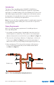
Introduction The Uponor Three-way Mixing Valve (A3040075, A3040100) is a microprocessor-controlled valve designed to regulate the supply water temperature to a radiant heating system by modulating the position of the valve. Mixed supply setpoint can be configured to reset from the outdoor air temperature. An optional boiler sensor can be used to provide boiler protection in non-condensing boiler applications.
Application The Uponor Three-way Mixing Valve can be used to mix the hot boiler water temperature with the cooler return water temperature from the system loop. The position of the valve is modulated to inject different rates of hot water into the cool system return water. This allows the heating system to receive virtually any water temperature.
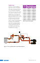
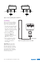
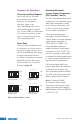
B A Return A Supply B Supply Mix Return Mix Figure 3: Three-way Mixing Valve Installations Installation Refer to the following installation instructions to properly install the Uponor Three-way Mixing Valve. Boiler Supply Outdoor C R Power Input Sensor Common Wall 1. The valve body can install in any position and orientation. Install the power connections over the supply port to ensure proper flow direction (see Figure 3). 2.
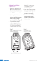
Actuator Installation and Removal 1. The actuator can attach to the valve body in either direction with the power connections over the supply port to ensure proper flow direction. 2. To remove the actuator prior to soldering, rotate it counterclockwise approximately 30 degrees and lift upward approximately ¾" (see Figure 5). Note: The D-shaped stem design allows for correct insertion every time. 4.
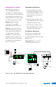
Powering the Control Intermittent Operation All terminals on the Uponor Three-way Mixing Valve are removable. To prevent damage to the electronics, disconnect all plugs before applying power and check voltages and sensors. After testing the circuits, plug in the terminals. 1. Connect the two wires on the end switch of the Uponor Zone Control Module (ZCM) to the R and W terminals on the Uponor Pump Relay. Warning: Make all wiring connections in accordance with applicable electrical codes.
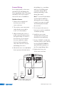
Sensor Wiring Do not apply power to the sensor terminals as this will damage the Three-way Mixing Valve. The wiring terminals for the sensors may be removed for ease of installation. Outdoor Sensor 1. Remove the screw and pull the front cover off the sensor enclosure. 2. The outdoor sensor can mount either directly onto a wall or in a 2" x 4" electrical box. 3. When mounting the sensor to a wall, ensure the wiring enters through the back or bottom of the enclosure.
General Tips for System Supply and Boiler Return Sensors •• Strap the sensors directly to the pipe using a cable tie. •• Place insulation around the sensor to reduce the effect of air currents on the sensor measurement. •• Place the sensors downstream from a pump or after an elbow or similar fitting. N ote: This is especially important if the system is using large-diameter pipes because the thermal stratification within the pipe can result in erroneous sensor readings.
Sequence of Operation Power Up and Heat Request Upon power up, the LED turns green and the control starts operation. For intermittent operation, power to the Three-way Mixing Valve can be switched through an end switch (e.g., Uponor ZCM) or a thermostat. For continuous operation, power can be connected directly to the Three-way Mixing Valve. Reset Ratio Once the Three-way Mixing Valve is powered up, it provides outdoor reset at the supply sensor location.
Minimum Boiler Return Temperature (DIP Switch 3) Warm Weather Shut Down (WWSD) (DIP Switch 4) The boiler protection function prevents low temperatures back to the boiler (provided a boiler sensor is installed). Warm Weather Shut Down (WWSD) function closes the Three-way Mixing Valve when the outdoor temperature is warmer than 70°F (21°C). WWSD is enabled by turning DIP Switch 4 to the on position. The green LED slowly flashes to signal the WWSD status.
Outdoor Reset To properly control a hot-water heating system, the heat supplied to the building must equal the heat lost by the building. •• The heat supplied to the building is directly proportional to the temperature of the water and the surface area of the 1.6 190 (88) 1.4 1.2 170 (77) 1.0 150 (65) 0.8 130 (54) 0.6 110 (43) 0.4 Supply Water Temperature 2.2 1.8 2.0 210 (99) 90 (32) 0.
Troubleshooting As in any troubleshooting procedure, it is important to isolate a problem as much as possible before proceeding. When the control flashes an error message, identify the fault and follow standard testing procedures to confirm the problem. If you suspect a wiring fault, return to the wiring section in this installation guide and carefully check all external wiring and wiring connections. LED Status Description Green Solid Power is on.
Setting Adjustments Important! Ensure the wires from the sensor are not connected to the Three-way Mixing Valve while performing this test. Remove the wiring terminals by gently pulling them from the Three-way Mixing Valve. If the outdoor temperature is cold and the building is cold, increase the Reset Ratio setting by one notch per day. Sensor Testing Refer to the steps below to properly test the sensors.
Product Specifications Maximum Operating Pressure: 300 psi (2,100 kPa) Maximum Shutoff Pressure: 125 psi (875 kPa) Fluid Temperature Range: 20º to 240ºF, (-7º to 115ºC) at 135ºF (57ºC) ambient Service: Closed-system hot and chilled water, up to 50% glycol Seat Leakage: Drop-tight close-off Electrical Rating: 24 VAC ±10%, 60 Hz Important! Do not exceed number of valves per transformer rating. For example, do not use more than five (5) Three-way Mixing Valves per 40VA transformer. Power Consumption: 7.
Materials of Construction Actuator Body: High-performance Engineered Polymer Gears: High-performance Internally Lubricated Engineered Polymer Valve Body: Forged Brass Stem: Brass Press Ring: Brass Ball: Brass (Chrome Plated) Seat: Modified Teflon® O-rings: EPDM Valve Size A B C D E Weight ¾" 3" 23⁄8" 53⁄8" 29⁄16" 4¾" 1.5 lbs. 1" 3" 2 ⁄8" 6 ⁄8" 2 ⁄16" 7¼" 1.5 lbs.
Three-way Mixing Valve Installation Guide 15
MKT10024_AB 3WayMixVlv_InsG_H478_0214, Copyright © 2014 Uponor. Printed in the United States Uponor, Inc. 5925 148th Street West Apple Valley, MN 55124 USA Tel: 800.321.4739 Fax: 952.891.2008 Uponor Ltd. 2000 Argentia Rd., Plaza 1, Ste. 200 Mississauga, ON L5N 1W1 CANADA Tel: 888.994.7726 Fax: 800.638.9517 www.uponorpro.