
User Guide

Uponor Heat-only Thermostat with Touchscreen l 3
Note: Avoid mounting the thermostat on a return-air chase or
where the temperature inside the wall differs from the room
temperature. If that is unavoidable, it may be necessary to plug
or seal the wire hole opening to prevent the environment inside
the wall from affecting the thermostat’s readings.
Wiring
Caution: Disconnect electrical power to the system to
prevent electrical shock and damage.
1. Remove
3
⁄16" of
insulation from the
wire ends. Ensure
the wire ends are
clean, dry and free
from corrosion.
2. Connect the power
wires to the Rh
and W terminals.
This corresponds
to terminals 2 and
3 on the Uponor
Zone Control
Module (A3031003
or A3031004). The
RH and W terminals
are not polarity sensitive.
3. Connect the optional oor sensor to the
SEN1 and COM terminals.
Note: The oor sensor is detected when power is rst applied to
the thermostat. Connecting the oor sensor with power applied
will prevent the oor functions from operating and may damage
the thermostat.
Important! Do not connect power to the oor sensor terminals
as damage to the device may occur.
Attaching the thermostat to the back plate
1. Locate the tabs and holes on the controller and back plate.
2. Align the back plate tab with the controller holes by leaning
the top of the controller on the back plate until it hooks.
3. Gently hinge the bottom of the thermostat onto the wiring
terminals until the thermostat engages with the terminal
connectors.
4. Use gentle pressure on the bottom of the thermostat until the
controller clicks into its locked position.
Important! Only gentle pressure is needed to engage the
controller onto the back plate. If resistance is felt, realign
the controller to the left or to the right to ensure the controller
pins are correctly aligned with the terminals. Do not apply
extreme pressure to the display area as damage to the
equipment may result.
Installing the oor sensor (optional)
The oor sensor (A9010599) comes with a 10-ft. wire. Install
the sensor and wire in a manner so it can be replaced should
it fail. If additional wire is needed to connect the sensor to the
thermostat, use 24/2 AWG. Uponor recommends installers
solder the connections (versus wire nuts) and place the
connections in an accessible junction box.
• Concrete/lightweight applications — If installing a oor
sensor in a lightweight application, make sure the sensor is
installed within a conduit (without splices) for easy removal
and replacement should the sensor fail. The oor sensor and
conduit should be placed equidistant between two parallel runs
of pipe for optimal sensing and control.
• Joist Trak™ installation — When installing a oor sensor
beneath the suboor and the surface above is nished, cut
a piece of 1" rigid insulation a minimum of 6" x 6". Cut a ¼"
groove from the outside edge to the center of the insulation.
Insert the oor sensor into the insulation and run the sensor
wire through the channel. Attach the insulation to the suboor
with adhesive or other suitable material. Make sure the sensor
is placed in the center of the joist, between the two plates.
• Quik Trak
®
installations — Prior to the nished ooring
being installed over the Quik Trak panels, cut or router a ¼"
groove into the suboor to accommodate the sensor and wire.
Route the wire to a location where the sensor can be wired
into the thermostat.
Testing the sensor — The oor sensor should be tested
prior to pouring concrete, closing up a ceiling or installing the
nished ooring. The installation will require a multimeter and
digital thermometer to properly test the resistance (ς) through
the sensor wires. Using the thermometer, read or measure
the temperature around the oor sensor location. Using the
multimeter, measure the resistance between the two wire leads
of the sensor. (Note: The wires should NOT be connected to
the thermostat.)
Compare the resistance value read on the meter to the value
on the table based on the temperature on the thermometer. The
values do not have to match but they should be close. If the
value on the meter is reading high, check for broken wires or a
bad sensor. If the value is reading low, there may be moisture
inside the sensor or the wiring is shorted.
Sequence of operation
This thermostat is designed to control hydronic radiant
applications. The dynamics of these types of systems differ
from a typical forced-air furnace or baseboard heating
application. A radiant system heats the mass and the objects
in the room. This thermostat uses fully automatic differential
and pulse width modulation (PWM) control functions to ensure
zone is comfortable and energy efcient.
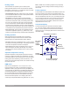
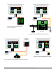
A3100101 Uponor Thermostat with Floor Sensor
A9010599
Floor Sensor
(Optional)
Sen1 Com W R
A3031003-4 Zone
Control Module
R
C
ES
ES
2 3 4
R1 R2 Y1 Y2