R a d i a n t F lo o r H e at i n g S y s t e m s R a d i a n t R e a d y 3 0 E TM installation guide A complete radiant mechanical room designed in a compact, preassembled, easy-to-install panel
ii www.uponorpro.
Radiant Ready 30ETM Installation Guide Table of Contents Section 1: Overview. . . . . . . . . . . . . . . . . . . . . . . . . . . . . . . . . . . . . . . . . . . . . . . . . 1 Section 2: Installation Requirements . . . . . . . . . . . . . . . . . . . . . . . . . . . . . . . . . . . Required Components. . . . . . . . . . . . . . . . . . . . . . . . . . . . . . . . . . . . . . . . . . . . . . . . . Main Power Supply Wiring. . . . . . . . . . . . . . . . . . . . .
Maintenance Guidelines (Contractor) . . . . . . . . . . . . . . . . . . . . . . . . . . . . . . . . . . . . Glycol Maintenance. . . . . . . . . . . . . . . . . . . . . . . . . . . . . . . . . . . . . . . . . . . . . . . . Replacing Pump or Pump Cartridge Assembly . . . . . . . . . . . . . . . . . . . . . . . . . . . Replacing the Expansion Tank . . . . . . . . . . . . . . . . . . . . .
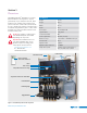
Section 1 Overview The Radiant Ready 30ETM (A3503000) is a complete radiant mechanical room designed in a compact, preassembled, easy-to-install panel. The unit, which includes a boiler, manifold, pump, expansion tank, pressure-relief valve, isolation valves, thermostat and air vent, is already wired, plumbed, tested and ready to be installed. Simply attach the panel to a wall, connect the radiant loops, attach the thermostat and connect the 240V electrical power. Specifications Weight 119 lbs.
2 www.uponorpro.
Section 2 Installation Requirements Required Components Note: For additional zoning options, see Section 11: Customization Options. Included with Unit • One (1) Uponor Heat-only Thermostat (A3030101) For additional thermostat options, see Section 11: Customization Options. Main Power Supply Wiring • One (1) Outdoor Temperature Sensor (A3503015) arning: Refer to local codes for wiring W requirements and always have a qualified electrician perform all electrical wiring.
4 www.uponorpro.
Section 3 Mounting After unpacking the Radiant Ready 30E, check the contents to ensure the following are included. If any contents are missing or damaged, contact your Uponor sales representative or distributor for assistance.
6 www.uponorpro.
Section 4 Electrical Power Connections al W min Ter All electrical connections are inside the boiler unit. To access, first remove the Radiant Ready 30E cover, then remove the boiler cover. Terminal Rh Required Tools • Wire cutter • Wire stripper • Standard screwdriver • Small jeweler’s screwdriver Figure 4-2: Wire the Thermostat Wiring Wire the Thermostat Connect both Uponor Heat-only Thermostat (A3030101) wires to the TT terminals on the unit.
Note: The Radiant Ready 30E is prewired with the pump connected to the CC boiler terminals. The Uponor Heat-only Thermostat (A3030101), Outdoor Temperature Sensor (A3503015) and high-voltage lines must be wired in the field. Wiring Diagram Figure 4-5: Radiant Ready 30E Wiring Diagram 8 www.uponorpro.
Section 5 Piping Connections Note: If your jurisdiction code requires a hardplumb port, see the Hard-plumb Port instructions in Section 11: Customization Options. Tubing Types For radiant installations, the tubing must be one of the following.
System Fluid For radiant installations, use one of the following two fluid options. • Water • Propylene-glycol/water mix, not to exceed 50% glycol, by volume NOT use methanol or ethylene glycol. DO These fluids may damage the Radiant Ready 30E components.
Section 6 Filling and Purging I mportant! Read through the following Filling and Purging Procedure before starting the process. This is extremely important as some steps in the process are required to be done quickly and will not allow time for pausing to read up on the next step. Additionally, a wrong move in the process could result in a faulty installation where the process must be performed all over again.
8. Open the hose valve on the return manifold (top) E to allow air to escape once the purging process begins. 4. Close all supply and return manifold ports by turning the valves clockwise D , G and H . (Remember to pull up the lock ring.) 5. Attach the fill hose to the connection on the supply manifold (bottom) F , and the drain hose to the connection on the return manifold (top) E . Note: First time opening the valve, the O-ring might be stuck.
I mportant! The following three steps must be done quickly, because if the system pressure gets too high (approximately 30 psi), the Temperature and Pressure Relief may release. This will result in a loss of fluid from the system as well as a wet work environment. Note: After 2 to 3 weeks, all air should be purged from the system. Go ahead and close the automatic air vent B . 11. Close the return valve on the first loop G . 12. Close the supply valve on the first loop H . 13.
14 www.uponorpro.
Section 7 System Startup I mportant! Before starting up the system, make sure the system temperature settings are correct. If extremely hot water circulates through the loops, it may damage the flooring. This is especially important with hardwood or engineered hardwood floors. Determine the following settings before commencing the startup sequence. Boiler Setpoint 1. Determine the temperature setting. The radiant system design will calculate the supply water temperature.
6. Trigger the pump to run by pressing the Tool button for two seconds to access the configuration field. Then press the Tool button three times to select the pump icon . After selecting the pump, press the + button to select ON. 7. Check the flow meters on the manifold and balance, if required (see Step 8). 12. Return pump delay back to desired setting by pressing the Tool button for two seconds to access the configuration field. Then press the Tool button three times to select the pump icon . 13.
Section 8 Basic Operation and Maintenance Basic Operation and Maintenance (Homeowner) Startup 1. Check system pressure and compare to pressure at the time of shutdown. A significant loss of pressure may indicate a leak in the system. 2. Check the system for signs of leakage. 3. Make sure all valves are in the open position. 4. Check to make sure the unit has power. The display should be illuminated. 5.
As the system ages, the inhibitors breakdown, causing the system pH to drop. Consult the glycol manufacturer for instructions on adding inhibitors to the system. Note that the system will reach a point where it will require a complete flush and refill. Ensure an Uponor-trained installer performs this maintenance. Propylene-glycol is the only type of glycol Uponor recommends in a radiant system.
8. If the system pressure is below 12 psi (0.82 bar), add more fluid to the system. Refer to Section 6: Filling and Purging for details. 9. Check for leaks. 10. Turn power back on to the unit. Replacing Fuses Inside the Unit Refer to the following instructions to properly replace fuses inside the unit. 8. Remove wires to heating elements at the left side of the boiler. 9. Remove the insulation piece. 10.
20 www.uponorpro.
Section 9 Boiler Control Settings The boiler control offers two modes of operation: Fixed Setpoint and Outdoor Reset. Outdoor Reset Mode (Outdoor Sensor Installed) I mportant! When running in Outdoor Reset mode, connect the Outdoor Temperature Sensor (A3503015) to the unit before applying electrical power to the unit. For wiring instructions, see Section 4: Electrical Power Connections.
Control Operation Target Temperature Fine Adjustments The boiler control features four push buttons at the bottom of the display to select and adjust parameters. Pressing the – and + buttons can offset the programmed target temperature without going through the Tool menus. When pressing the – and + buttons, the value “0” will appear and blink to show a “0” offset value from the original settings.
Note: The boost program works best in applications with a limited number of room thermostats. For applications with several room thermostats, the heat demand during very cold periods may not be adequately satisfied. Cancelling Boost 2. Select ON or OFF using the + or – buttons. To cancel the Boost program, refer to the following instructions. 1. Press the Tool button for six (6) seconds. The display will show the Boost icon (up arrow) and two options, ON or OFF, will blink.
I mportant! If using temperature-sensitive floor coverings, such as hardwoods, contact Uponor Technical Services before activating the Boost system. Damage to flooring can result from water temperature that is too high. technical.services@uponor.com U.S.: 888.594.7726 Canada: 888.994.
Section 10 Troubleshooting Issue Cause Solution No heat 1. No call for heat from the thermostat 1. Make sure the thermostat is connected correctly. Make sure setpoint is at the desired level 2. Loop valves are not open 2. Make sure all valves are open and, if necessary, balanced. 3. No power to the heat source or broken heat source 3. Make sure the breaker for the unit hasn’t tripped. If not, make sure the unit is wired correctly. Make sure there is a call for heat (from the thermostat).
Troubleshooting (continued) Issue Cause Solution No or low pressure 1. Not enough pressure at startup 1. After filling and purging, the pressure was not set at designed pressure level. Add fluid to the system to raise the pressure level. Be aware, this may require a complete fill and purge procedure since air might enter the system during the filling process. Note: Close all loops before starting the fill (this will prevent air from entering the loops, requiring only the unit to be purged). 2.
Troubleshooting (continued) Issue Cause Solution High pressure 1. Too much system pressure at startup 1. After filling and purging, the pressure was set above designed pressure level. Drain some fluid out of the system to obtain designed pressure level. Note: Differences in temperature may cause the system pressure to rise slightly after startup. 2. Incorrect auto fill setting 3. Heater malfunction 2. The auto fill valve needs to be set at designed system pressure.
Troubleshooting (continued) Issue Cause Solution Leaks 1. Staining 1. Staining can be a sign of a leak in the system; further investigation is required to follow the source of the leak. 2. Mineral buildup 3. Wet spots 2. Mineral buildup is a sign of a small leak in the system; generally the deposit is located near the leak. Try tightening the affected fitting connection. Small mineral buildups in a system is tolerable, as the deposits take a long time to form.
Troubleshooting (continued) Issue Cause Solution Low flow 1. Closed manifold valves 1. If the pump is on and there is low flow to all loops or a specific loop, check the valves at the end of each loop. the return manifold valves should be fully open and the supply manifold valves should be balanced. 2. Closed isolation valves 3. Zoning valves (actuators) 4. Air in the system 5. Faulty pump 2.
Troubleshooting (continued) Issue Cause Solution Unit not turning off 1. Thermostat setting is too high 1. If the thermostat(s) setpoint(s) are incorrectly set too high, there will be a call for heat and the boiler will continue to heat the area until the thermostat is satisfied. 2. Faulty controls 3. Faulty boiler 4. Faulty wiring 2. If the thermostat is wired incorrectly, the boiler may see the thermostat/relay as calling for heat, when in reality there is no call. 3.
Section 11 Customization Options Hard-plumb Port • Using the Climate Cŏntrol Multifunction Controller This is a radiant system which includes a boiler. Some jurisdictions may require adding a fill to the system. The fill can be attached to the hard-plumb port located behind the return manifold (see Figure 11-1). All fills (automatic or manual, as dictated by code) must be purchased separately.
block wired to the thermal actuator it is controlling. To fire the boiler on a call for heat, ensure the end switch (ES) output of the ZCM is wired to the TT terminals of the boiler. Climate Cŏntrol Zoning System The Climate Cŏntrol Zoning System is another option for controlling separate heat zones. The Zoning System uses Uponor Two-wire Thermal Actuators (A3030522). Each actuator must be wired to a set of quick connectors on the Zoning System base unit (see Figure 11-2).
Manifold Options This section details the following manifold options. • Adding manifold loops • Moving the manifold out of the cabinet • Running multiple remote manifolds • Supplying a submanifold from the primary (unit) manifold Adding Loops It is possible to add up to three (3) additional loops to the manifold.
Moving the Manifold Out of the Cabinet 8. Remove the elbow directly below the pump, so the distribution piping is parallel to the wall. Required Components 9. Rotate the elbow clockwise, to point downward, so the distribution piping is parallel to the wall.
12. Attach a 3⁄4" male NPT x tubing connection to the 3 ⁄4" female NPT connection located just below the circulator pump flange and to the elbow that was rotated to face downward. Figure 11-8: Attach Connections 14. Attach a 3⁄4" male NPT x ProPEX/MLC tubing connection to each of the R32 male x 3⁄4" female NPT adapters, or use an R32 male x ProPEX/MLC tubing connection. 15. Reinstall the flat gasket and thread the R32 male x ProPEX/MLC tubing connection back onto the manifold. 16.
Running Multiple Remote Manifolds Running multiple remote manifolds is very similar to the process of running a single remote manifold outside the unit. The only exception to the process is adding tee and splitting the line so both manifolds can be fed independently of each other. The exact location of the tee does not matter as long as each manifold is run in parallel, so each can operate independently from one another. Refer to the following process to run multiple remote manifolds. 1.
Appendix Spare Parts List Part No. Part Description A3503001 Boiler Temperature Control A3503002 Power Relay Coil, 24VAC (contact normally open 30A) A3503003 Contactor, 4 Poles (coils 120V, contact 600V, 50A res.) A3503004 Time Delay Fuse (600V, 15A, class CC) A3503005 Fuse Block with Screw (600V, 1 pole, for class CC fuse) A3503006 Terminal Block, 600V, 3 Poles (115A, line 2-14, load 2-14) A3503007 Electric Element Square Flange, 4.
MKT10008-AA RR30E_InsG_H220_0411, Copyright © 2011 Uponor, Printed in the United States Uponor, Inc. 5925 148th Street West Apple Valley, MN 55124 USA Tel: 800.321.4739 Fax: 952.891.2008 Web: www.uponorpro.com Uponor Ltd. 2000 Argentia Rd., Plaza 1, Ste. 200 Mississauga, ON L5N 1W1 CANADA Tel: 888.994.7726 Fax: 800.638.9517 Web: www.uponorpro.