
Overview of Primary Product


Radiant Ready 30E Installation Guide
7
Section 4
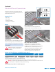
Electrical Power Connections
All electrical connections are inside the boiler unit.
To access, first remove the Radiant Ready 30E cover,
then remove the boiler cover.
Required Tools
• Wire cutter
• Wire stripper
• Standard screwdriver
• Small jeweler’s screwdriver
Wiring
Connect Power
Use a strain relief to connect the 240V power cable to
the unit. Connect ground, L1, L2 and neutral wires.
Note: All wiring must comply with electrical codes
and standards.
Caution: Disconnect electrical power to
the system to prevent electrical shock
and damage.
Wire the Thermostat
Connect both Uponor Heat-only Thermostat
(A3030101) wires to the TT terminals on the unit.
Wire Outdoor Reset (Optional)
If using outdoor reset, connect both Outdoor
Temperature Sensor (A3503015) wires to the SS
terminals on the unit. Note that Uponor recommends
18 AWG LVT wire to connect the Uponor Heat-
only Thermostat (A3030101) (maximum wire length
200 feet) and the Outdoor Temperature Sensor
(A3503015) (maximum wire length 300 feet).
Ratings and Specifications at 240VAC (single phase)
1
Radiant Ready 30E Cable 90C
2
Breaker
2
Capacity kW/BTU/h Amps Electric Element(s) Stage(s) Copper Aluminum Amp
9/30,710 37.5 2 x 4.5 kW 2 8 ga 6 ga 50
1 Electric supply with three conductors (L1, L2 and neutral) and ground.
2 Could require a higher-capacity cable depending on local codes. In all cases, the local electrical code has priority.
Warning: Local codes may require different size breakers or wire. In all cases, the local electrical code
has priority. Ensure a qualified electrician performs all wiring.
Terminal Rh
Figure 4-1: Connect Power
Figure 4-2: Wire the Thermostat
Figure 4-3: Wire Outdoor Reset (Optional)
Table 4-4: Ratings and Specifications at 240VAC (single phase)
Terminal W