RADIANT HEATING SYSTEMS QUIK TRAK® DESIGN AND INSTALLATION MANUAL Quik Trak® Design and Installation Manual
Table of Contents Uponor Quik Trak®. ...................................................................................................... 1 Quik Trak Calculations.................................................................................................. 2 Installation Methods.................................................................................................... 3 Quik Trak Over a Wood Subfloor with Hardwood Floor Covering..................................
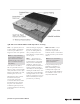
Uponor Quik Trak Uponor makes it easier to keep up with the demand for radiant heating with Quik Trak. This cost-effective, patented, wood-panel system is engineered for wood-frame construction and offers an alternative to joist heating and poured floor underlayment installations. Only 1 ⁄2" thick, Quik Trak adds minimal height to floors.
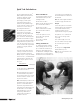
Quik Trak Calculations Uponor’s Advanced Design SuiteTM (ADS) software performs heat-loss calculations, guides the system designer through the radiant panel design, provides system requirements and generates a material list. This powerful design tool also offers the contractor a host of business tools for a variety of job-management functions. The calculation portion of ADS prompts the user to input the tubing type, the design differential temperature and the specifics of floor construction.
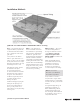
Installation Methods Quik Trak Over a Wood Subfloor with Hardwood Floor Covering How — Lay Quik Trak panels over a plywood subfloor perpendicular to the finished wood floor. Make sure to stagger the seams of the Quik Trak. Secure panels to the subfloor with 11⁄4" Quik Trak Screws or 1" staples. To start, secure the middle of the panel with a screw or staple. Work from the middle to the ends, alternating from side to side. After laying the panels, vacuum the debris from the panel grooves.
Quik Trak Over a Wood Subfloor with Tile/Linoleum Floor Covering How — Lay Quik Trak panels over a plywood subfloor perpendicular to the floor joists. Make sure to stagger the seams of the Quik Trak. Secure panels to the subfloor with 11⁄4" Quik Trak Screws or 1" staples. To start, secure the middle of the panel with a screw or staple. Work from the middle to the ends, alternating from side to side. After laying the panels, vacuum the debris from the panel grooves.
Quik Trak Over a Wood Subfloor with Carpet Floor Covering How — Lay Quik Trak panels over a plywood subfloor perpendicular to the floor joists. Make sure to stagger the seams of the Quik Trak. Note: For carpet installations, it is necessary to install 6" of plywood material around the perimeter of the room to allow space to install the tack strip and padding. Secure panels to the subfloor with 11⁄4" Quik Trak Screws or 1" staples. To start, secure the middle of the panel with a screw or staple.
Quik Trak Over an Existing Concrete Slab How — First, install a layer of 5 ⁄8" or 3⁄4" plywood subfloor over the concrete slab. Glue or power-nail the plywood directly to the concrete if a vapor barrier is not required. If a vapor barrier is required, then power-nail the plywood to the concrete slab. Lay Quik Trak panels over the plywood subfloor. Make sure to stagger the seams of the Quik Trak. Secure the panels to the subfloor with 1" screws or 1" staples.
Quik Trak Radiant Wall Installation How — Starting at the floor level on the outside wall, install Quik Trak panels parallel to the floor at a maximum of six rows high (42") to avoid interference with window and picture placement. Fasten panels to the studs on both sides of the groove with 1" drywall screws. After installing the panels, attach 1⁄2" furring strips to the remainder of the stud wall, to provide an even base for the sheetrock.
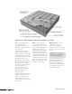
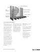
Quik Trak Design and Installation Wall Return Panel Quik Trak Panel 1⁄2"-thick 1⁄2"-thick Wood Filler Pieces Thinset Material Screed Level Manifold Planning the Quik Trak Installation In a concrete application, you can improve installation time by carefully planning the placement of manifolds and leaders. As shown above, the leaders must run above the floor. To save time, draw the Quik Trak layout on a piece of paper before you begin the installation. 1.
Piping Layout When Running Tubing Above the Floor Carefully plan the Quik Trak layout before installation begins. A wellplanned layout will result in equal loop lengths and minimal waste. Placement of the manifold is key to determining the layout. Manifolds can be placed either above or below the floor. Either location needs to be accessible by a service panel if the wall or ceiling below are finished. Figures 5 and 6 show manifold location in the wall because the floor is inaccessible from below (e.g.
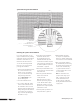
Piping Layout with Access from Below the Floor Figures 7 and 8 show manifold locations in the joist cavity. The entire floor area is accessible. The arrows illustrate the direction of water flow through the tubing. The dotted lines represent the supply and return lines that are beneath the floor. Figure 7: Manifold Location in the Joist Cavity Figure 8: Manifold Location in the Joist Cavity 10 www.uponorpro.
Panel Direction When possible, start with the warmest water on the exterior walls and progress toward the interior of the room. The direction of the panels in the layout dictate the tubing runs. Outside Wall Figures 9, 10 and 11 show the recommended layout for the panels. The arrows represent the recommended direction of the Quik Trak panels. Floor Joists Figure 9: For tile, parquet and linoleum finished floors, install Quik Trak panels perpendicular to the floor joists.
Preliminary Layout A After determining the direction of the Quik Trak panels, design the layout. 1. Mark any areas where panels will not be installed (e.g., kitchen cabinets). 2. From the wall, measure the width of the Return Panel plus 1⁄4" for a total of 71⁄4" (see Distance A). No Panels A 3. Snap a chalk line to outline each of the Return Panel walls (see Figure 12). 4.
Panel Installation (cont.) Begin the installation by laying down the Quik Trak panels and anchoring one side of a panel with a screw at both ends (see Figure 14). This allows for quick realignment, if necessary. Once the panels are properly placed, install screws on both sides of a panel. Use ten screws to ensure that the panels are secure (see Figure 15). Using the Quik Trak Installation Tool Kit (E6050000) will speed this process and alleviate strain from bending.
Final Floor Preparation Use 1⁄2" plywood or similar product to fill any small areas not covered by panels (see Figure 18). This will make for a completely level surface. When installing panels on a suspended wood floor with access from below, determine the locations of the supply and return holes to the manifolds (see Figures 7 and 8 on page 10). Note: Leader length is crucial when calculating the number of loops for a given room.
Tubing Installation (cont.) Once the tubing is attached to the supply manifold, secure the 3⁄8" Metal Bend Support to the tube where it comes out of the floor from the supply manifold. It is best to first secure the bend support on the side of the tubing that will remain below the floor. Then position the bend support at the desired point on the tubing and snap the tubing into place. Finally, push the bend support into the hole that you drilled in the Quik Trak groove.
Appendix A — Advanced Design Suite (ADS) Worksheet Project Information Project Name____________________________________________________ Date Received_ ___________________________ Project Location_ _________________________________________________ Date Design Due___________________________ Contact Person_ ________________________________________________ Contact Number_ __________________________ Design Information Notes Suspended Floors Outdoor design temperature Under-floor insulation R-value Def
Upward load (BTU/h/ft2) Total load (BTU/h/ft2) E F Quik Trak® Design and Installation Manual Quik Trak returns Loop 4 EE nter the “Floor Unit Load to Room” value from ADS printout (upward load). DE nter the amount of square footage used in the room. C Zone is equal to thermostat. I Refer to Appendix D for floor covering information. H The only tubing size available for Quik Trak is 5⁄16" Wirsbo hePEX. G (Row E/2) + Row B = floor surface temperature. Do not exceed 87.5°F /30.
Appendix C — Radiant Surface Temperature Charts Radiant Floor Surface Temperatures Room setpoint Floor Surface Temperature = (BTU/h/ft2 ÷ 2) + Room Setpoint 75°F 80.0 82.5 85.0 87.5 90.0 92.5 95.0 97.5 100.0 102.5 72°F 77.0 79.5 82.0 84.5 87.0 89.5 92.0 94.5 97.0 99.5 70°F 75.0 77.5 80.0 82.5 85.0 87.5 90.0 92.5 95.0 97.5 68°F 73.0 75.5 78.0 80.5 83.0 85.5 88.0 90.5 93.0 95.5 65°F 70.0 72.5 75.0 77.5 80.0 82.5 85.0 87.5 90.0 92.5 60°F 65.0 67.
Appendix D — R-value Charts Construction Materials ⁄8" 1 ⁄4" 1 ⁄8" 3 ⁄2" 1 ⁄8" 5 3 ⁄4" ⁄8" 1 Wood Flooring ⁄4" 1 ⁄8" 3 ⁄2" 1 ⁄8" 5 ⁄4" 3 Plywood (Douglas fir) 0.31 0.47 0.62 0.77 0.93 Ash 0.35 0.47 0.59 0.71 Oriented strand board (OSB) 0.31 0.47 0.62 0.78 0.94 Cherry 0.35 0.46 0.58 0.69 Elm 0.33 0.45 0.56 0.67 0.66 0.82 Redwood 0.51 0.68 0.84 1.01 Maple 0.35 0.46 0.58 0.69 Oak 0.33 0.45 0.56 0.67 Walnut 0.34 0.45 0.57 0.
Appendix E — Supply Water Temperature Charts Quik Trak Radiant Floor 65ºF Room Setpoint Temperature Floor Covering Rv BTU/h/ft2 Rv = 0.25 Rv = 0.50 Rv = 0.75 50 Rv = 1.0 45 40 Rv = 1.5 35 Rv = 2.0 30 Rv = 2.5 25 Rv = 3.0 20 15 10 5 0 80 Differential Temperature 20ºF 90 100 110 120 130 140 150 160 170 180 Supply Water Temperature Note: Uponor’s recommended maximum design temperature is 165ºF.
Appendix F — Flow Chart Refer to the following instructions to determine the flow per loop for a room. • The room is 12 ft. by 12 ft. with the tubing installed at 7" o.c. The load for the room is 40 BTU/h/ft2. The room is 15 ft. from the manifold location. 100% Water at 120ºF (48.9°C) 20ºF (11.1°C) Supply/Return Differntial Flow in GPM Per Foot of Tubing BTU/h/ft2 7" tubing on-center distance BTU/h/ft2 7" tubing on-center distance 50 0.00296 27 0.00160 49 0.00290 26 0.00154 48 0.00284 25 0.
Appendix G — Hydronic Friction Loss Table ⁄16" Uponor PEX-a — 100% Water — Feet of Head per Foot of Tubing 5 Velocity (ft./sec.) GPM 80ºF 27ºC 90ºF 32ºC 100ºF 38ºC 110ºF 43ºC 120ºF 49ºC 130ºF 54ºC 140ºF 60ºC 150ºF 66ºC 160ºF 71ºC 170ºF 77ºC 180ºF 82ºC 190ºF 88ºC 200ºF 93ºC 0.5 0.10 0.00908 0.00873 0.00841 0.00814 0.00789 0.00767 0.00747 0.00729 0.00712 0.00697 0.00683 0.00670 0.00659 0.6 0.13 0.01230 0.01183 0.01141 0.01105 0.01072 0.01043 0.01016 0.00992 0.
Quik Trak® Design and Installation Manual 23
QuikTrak_InsMan_H471_0813, Copyright © 2013 Uponor, Inc. Printed in the United States Uponor, Inc. 5925 148th Street West Apple Valley, MN 55124 USA Tel: 800.321.4739 Fax: 952.891.2008 Uponor Ltd. 2000 Argentia Rd., Plaza 1, Ste. 200 Mississauga, ON L5N 1W1 CANADA Tel: 888.994.7726 Fax: 800.638.9517 www.uponorpro.