
Install Instructions


6
------------------------------------------------------------ Section 4 ------------------------------------------------------------------
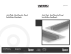
Joist Trak Heat-Transfer Panel
Installation
Joist Trak Installation
Install the Joist Trak panels with either screws or nails into the pre-
punched mounting holes. If available, a power nailer or screw gun
helps facilitate the installation process. Install the panels with a
minimum
¹⁄₄-inch gap between them to allow for expansion and
contraction. This gap can also be as wide as 5 inches to help
maximize the Joist Trak coverage area and minimize the amount of
panels that have to be cut to fit into the end of joist bays. The ends of
all joist bays require a minimum of 12 inches and a maximum of 18
inches to loop the tubing from panel-to-panel and bay-to-bay.
Note: Joist Trak panels are easily cut on a standard miter saw (with a
carbide blade) or with a hand hacksaw. Remove any burrs left
on the Joist Trak panels before installing them.
Installing the Tubing
Once the Joist Trak panels are installed, snap the tubing into the
channel of the panels. Use a rubber mallet to tap the tubing securely
into place. When working overhead, use a suitable length of
construction lumber (2" x 4") to push the tubing into place.
When drilling holes in joists for the tubing to pass from bay to bay,
allow sufficient clearance for sleeving of the tubing. Never exceed the
tubing’s minimum bending radius, and make sure the tubing does
not rub against the joist hole. See Chapter 5 in the Wirsbo CDAM for
more information about construction methods.
Insulation
Install fiberglass batt insulation below all Joist Trak installations.
Failure to provide suitable insulation decreases system efficiency and
may not allow for sufficient heat output. Install insulation tightly
against the Joist Trak panels to minimize air gaps between the
subfloor and the insulation.
3
--------------------------------------------------Section 3 ------------------------------------------------------------------
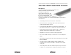
Joist Trak Heat-Transfer Panel Design
Design Notes
The Joist Trak heating system design incorporates many of the same
required calculations and parameters discussed in Chapters 7 and 8
of the Wirsbo Complete Design Assistance Manual (CDAM). However,
Joist Trak design utilizes a separate Water Temperature Chart (see
chart on page 4) and uses a simple material calculation formula for
the panels.
Step 1
Determine the Heating BTU/h Requirements
Perform a complete room-by-room, heat-loss analysis of the areas to
be heated using the Wirsbo Advance Design Suite
™
(ADS) software
package. (For information about radiant floor and ceiling system
design, see Chapters 7 and 8 in the Wirsbo CDAM or contact your
local wholesaler.)
Step 2
Determine the Required Heat Output
Once the heating requirement (heat loss) is known, use the following
formula to determine the BTU/ft
2
output required.
Heat Loss
Required Heat Output (BTU/ft
2
) = --------------------------
Net Area
(sq. ft.)
Step 3
Select the Tubing Size and Joist Trak Spacing
The Joist Trak system is generally based on an 8-inch on-center
design to accommodate the typical 16-inch on-center floor joist
construction found in most modern wood-frame structures. It is
possible to find 24-inch on-center spacing in older homes. As this
spacing is still a multiple of eight, 8-inch on-center Joist Trak spacing
remains applicable.
Discuss construction practices and joist spacing that differ from the
above, as well as structures with low-heating requirements with an
experienced designer to determine acceptable Joist Trak spacing and
system alternatives.