
Install Instructions


Step 5
Calculate the Tubing and Joist Trak Panels Needed
Tubing
Multiply the net area by 1.5 to determine the tubing required for
8-inch on-center spacing. Be sure to include the supply and return
runs to the manifold location.
Joist Trak
Multiply the total length of tubing by 0.85. This takes into account the
turns at the end of each run that are not used by Joist Trak. (Do not
include the supply and return runs to the boiler and manifold for this
calculation.) Divide this number by four (for 4-feet Joist Trak lengths)
to get the estimated number of Joist Trak panels required for the
area.
Number of Loops
The maximum circuit length for a Joist Trak loop is 200 feet for
³⁄₈" tubing and 300 feet for ¹⁄₂" tubing. The maximum area that can be
covered per loop using 8-inch on-center Joist Trak spacing, including
a 10-foot supply and return leader, is 186 sq. ft. using
³⁄₈" tubing and
247 sq. ft. using
¹⁄₂" tubing. Taking into account the supply and return
runs to the manifold location, determine the number of loops. If the
boiler location is a great distance from the area to be heated,
establish a remote manifold location.
Step 6
Calculate the Flow Rate and Pressure Drop
See Appendices G and H in the Wirsbo CDAM to calculate the flow
rate and pressure drop.
5
4
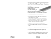
Joist Trak is available for either ³⁄₈" or ¹⁄₂" tubing. Larger tubing is not
used due to the common space constraints when working within joist
bays. Wirsbo recommends
³⁄₈" Joist Trak panels for installations below
the subfloor and other space-constrained applications. Use
³⁄₈" Joist
Trak panels for wall and ceiling applications as well.
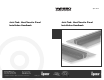
Step 4
Determine the System Supply-Water Temperature
Use the Joist Trak Water Temperature Chart (below) to determine the
system supply-water temperature.
1. Find the required Joist Trak output on the left side of the chart
and extend a line to intersect with the floor covering R-value
line.
2. From this intersection, extend another line straight down. Find
the supply water temperature at the bottom of the chart.
3. If the supply water temperature is above 160°F, or if the surface
temperature is above 87.5°F:
a. Check the heat-loss calculations for accuracy.
b. Choose a floor covering with a lower R-value if possible.
c. Reduce the heat loss of the area (e.g., increased insulation,
new windows).
d. Include supplemental heating for the area (e.g., Joist Trak
wall or ceiling heating, baseboard, air handler, etc.).
BTU/ft
2
Water
Temperature
Floor Covering
R-Valve
Water Temperature Chart
Based on 8-inch On-center Spacing