I N D O O R C L I M AT E UPONOR CONTROL SYSTEM Uponor Control System – Installation and Operation Manual 01 | 2009
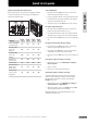
UK English Installation and operation manual Quick start guide ..............................................................3 6 Reset controller .................................................................30 Deregister channels in controller .......................................30 Reset Interface I-75/76 ...................................................30 Preface ...............................................................................6 Copyright and disclaimer ..........................
Quick start guide UK English Quick start guide This is a quick start guide to serve as a reminder for experienced installers. We strongly recommend reading the full manual before installing the Uponor Control System. Install antenna Using the 15 m four-wire connector cable or similar: • Connect the antenna to terminals 9 and 10 on the controller (non-polarized). • • Attach the antenna to a wall or the rear of the controller.
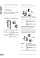
Quick start guide Register thermostats Optional: install multiple controllers UK English Up to three controllers can be interconnected. This is only possible if an Uponor Interface I-75/76 is used. 1 Connect terminals 5 and 6 on controller 2 to terminals 5 and 6 on controller 1 (polarized). 2 If a third controller is needed, then connect terminals 7 and 8 on controller 3 to terminals 7 and 8 on controller 1 or 2 (polarized). When connecting multiple controllers, all controllers must have IDs.
Register thermostat with external sensor Test communication Before the thermostat is registered, the configuration switches on the thermostat must be set according to the way Uponor Thermostat T-54 will be used: 1 Press and release the Test button on the controller. The LEDs for all registered channels come on. 2 Press the registration button of each registered thermostat. If communication is good, then the LEDs for the channels registered to the thermostat go off.
UK English Preface The Uponor Control System Installation and Operation Manual describes how to install and operate the components of the system. Conventions used in this manual The following symbols are used in the manual to indicate special precautions when installing the Uponor Control System: STOP WARNING Risk of injury. STOP WARNING The Uponor Control System uses 50 Hz 230 V AC power. In case of emergency, immediately disconnect the power.
Uponor has prepared this Uponor Control System Installation and Operation Manual and all the content included ("Manual") solely for information purposes. The contents of the Manual (including graphics, logos, icons, text, and images) are copyrighted and protected by worldwide copyright laws and treaty provisions. You agree to comply with all copyright laws worldwide in your use of the Manual.
UK English 8 U P O N O R C O N T R O L S Y S T E M – I N S TA L L AT I O N A N D O P E R AT I O N M A N U A L
The Uponor Control System is a management system for underfloor heating systems. Comfort and temperature control for each room can be combined through the various components. Uponor Interface I-75 or Uponor Interface I-76 can be added to facilitate system optimization. Note that Uponor Interface I-76 is compatible only with Uponor Controller C-56, and Uponor Interface I-75 is compatible only with Uponor Controller C-55. 1.1 UK English 1.
1.2 Components of Uponor Thermostat T-55 Thermostats T-75, T-55, and T-54 Public The thermostat temperature settings are adjusted using the dial, which is removed to set minimum/maximum temperatures. The 21°C position is marked with a larger line.
Interface I-75/76 1.4 Components of Uponor Interface I-75/76 Interface with controller kit Uponor Interface I-75/76 can be purchased in a kit together with Uponor Controller C-55/56. UK English 1.3 Uponor Interface I-75/76 enables centralised and optimised management of the Uponor Control System. 1 2 1 2 4 3 4 3 5 6 9 The table below describes the components of Uponor Interface I-75/76. The item numbers correspond to the numbers in the illustration.
1.5 Accessories UK English Uponor offers a wide variety of accessories for use with the standard portfolio. 1 5 3 6 2 4 7 8 9 10 11 The item numbers in the table below correspond to the numbers in the illustration.
Uponor Control System Uponor Interface I-75/76 Uponor recommends following the process described below to guarantee the best possible installation results. Follow the process described below to install the Uponor Interface I-75/76.
UK English Example installation 2.1 In the example installation illustrated below, the Uponor Thermostat with display T-75 01 controls channels 01a, 01b and 02a, 02b. The external sensors attached to Uponor Thermostat T-54 Public 01 and 10 communicate the floor temperature to the Uponor Controller C-55/56. The Uponor Thermostat with display T-75 03 controls channels 03 and 04.
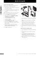
Refer to the installation preparation guidelines (see section 2.1 on previous page), and use the following guidelines when positioning the controller: • Position the controller just above the manifold. Check the position of the 230 V power outlet. • Check that the cover of the controller can be removed easily. • Check that connectors and switches are easily accessible. UK English 3.
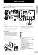
3.3 Connect components to controller 3.4 UK English Refer to the wiring diagram in the fold-out of this document. The illustration below shows the inside of Uponor Controller C-55/56. Optional: connect heating/cooling input If the system is equipped with a cooling unit (requires additional products), the Uponor Control System can manage the heating/ cooling switch input with the controller.
Optional: connect pump management The Uponor Control System can operate a circulation pump, which stops when there is no demand for heating or cooling. See the circulation pump supplier documentation and the relevant Uponor wiring diagram before performing the connection. A pump for all manifolds and controllers can be connected to the closest controller. UK English 3.
3.7 Test actuators UK English Uponor Controller C-55/56 manages the temperature set point. When a temperature change occurs, the actuator opens or closes the valve to adjust the heat supply. To test the actuators: 1 2 18 Press the button of the selected channel. • The LED comes on, which means that the controller receives a signal and powers the actuator on the selected channel. The time for actuator opening is about 5 minutes.
Label room thermostats Label the thermostats with the channel numbers they are to control, for example, 02, 03. For a system with Uponor Interface I-75/76 and several controllers, add the ID of each Uponor Controller C-55/56, for example, 1.02, 1.03, 2.02, 2.03. For Uponor Thermostat T-54 Public, add information for floor or outdoor sensors when applicable. The illustration below shows where to label the thermostats. 4.1 UK English 4.
Wire external sensor to Thermostat T-54 Public Example installation with floor sensors UK English The example below shows an installation of thermostats in a room with floor sensors. Uponor Thermostat T-54 Public 01 and 10 are connected to floor sensors. 1 2 24 V 24 V 24 V 24 V 24 V 24 V 24 V 24 V 1 Connect cable from the floor or outdoor sensor (nonpolarized).
Register thermostats in controller The illustration below shows how to register the various room thermostats associated with Uponor Controller C-55/56. 4.3 Install Thermostat with display T-75 Attach to wall UK English 4.2 The Uponor Thermostat with display T-75 can be attached to a wall with screws or adhesive strips, as shown in the illustration below. To register room thermostats in the controller: 1 Press and release the Test button. The test LED comes on.
4.4 Install Thermostat T-54 Public and T-55 4.5 Uponor recommends testing the communication between the thermostats and the controller after installation. Attach to wall UK English Test communication Uponor Thermostat T-54 Public and T-55 can be attached to a wall with screws or adhesive strips, as shown in the illustration below. The illustration below shows the location of the test button of the controller and the registration buttons of Thermostat T-54 Public, T-55 and T-75.
Refer to the installation preparation guidelines (section 2.1 Prepare for installation on page 14). Uponor Interface I-75/76 can be attached to a wall or to the cover of the controller. UK English 5. Install Uponor Interface I-75/76 Attach Interface I-75/76 to bracket The illustration below shows how to attach Uponor Interface I-75/76 to the bracket. Additional controllers must be installed for installations with more than one manifold or more than 12 channels.
Use 15 m installation cable 5.2 UK English If Uponor Interface I-75/76 is more than 2 m from Uponor Controller C-55/56, use the 15 m four-wire connector cable or similar, as shown in the figure below. Optional: connect multiple controllers STOP Note that multiple Uponor Controller C-55/56 units require software programming. Up to three controllers can be connected to the same Uponor Interface I-75/76. All controllers require an antenna, as shown in the illustration below.
Use navigation keys 5.5 Each of the five navigation keys on Uponor Interface I-75/76 has dual functions, as described in the table below. Key Functions Displays next menu The Set Date/Time screen opens automatically when the language is set.
5.6 Access Installer level 5.7 UK English Uponor Interface I-75/76 has three access levels (Interface I-76 displays these icons only): Basic Optional: set controller IDs Controller IDs are required only when two or three controllers are used. The IDs can be set only when Uponor Interface I-75/76 is set to Installer level access. To set controller IDs for Interface I-75/76: Advanced 1 On the Uponor screen, select Main Menu > Settings > System Parameters > Controller ID.
Display actuator status To display actuator status: 1 Set Interface I-75/76 access to Installer level. 2 On the Uponor screen, select Main Menu > Information > Rooms. 3 Select the desired room and press OK. The screen displays the Actuator status: • OK – Normal operation. • Alarm – A short circuit or similar problem is reported. 5.11 Optional: activate cooling management Cooling mode must be activated in Uponor Interface I-75/76 if cooling is installed (requires additional product).
UK English 5.13 Complete Interface I-75/76 installation 5.15 Optional: auto-balance (Interface I-76 only) The illustration below shows how to complete the Uponor Interface I-75/76 installation. The auto-balance function removes the need for manual balancing of the manifold at installation. The principle for automatic balancing is that the energy required by each loop is distributed in pulses. The length of the pulses in each loop is calculated from the actual heat demand of the room.
5.17 Supply diagnostics (Interface I-76 only) 1 On the Uponor screen, select: Main Menu > Settings > System Parameters > Supply Diagnostic. 2 On the Supply Diagnostic screen, select Activate and press OK. UK English Supply diagnostics is a help function that can be activated in Uponor Interface I-76. It monitors the behaviour of the system and issues a warning if the system is under- or overpowered. Underpowered means that the system cannot reach its set point in one or more zones.
UK English 6. Troubleshoot installation The table below describes troubleshooting after installation. Failure Indication Causes Solution System does not start Power LED off in Uponor Controller C-55/56 No voltage Check that the controller is connected to the AC power and that the wiring in the 230 V compartment is correct Poor radio reception Repeated radio alarms Antenna installed inside a metal cabinet or too close to other shielding objects Change the antenna location.
If no Uponor Interface I-75/76 is connected to the system, then Uponor recommends occasionally opening the controller cover to check for alarms. The controller LED flashes continuously for general alarms, so it is necessary to determine which thermostats are issuing alarms. 7.1 The table below describes the status of the controller LEDs.
UK English 8. Operate Uponor Thermostats Batteries for thermostats Change temperature format All thermostats use two alkaline 1.5 V AAA batteries. Ensure that the batteries are correctly inserted in the thermostats. To change the temperature format to Celsius or Fahrenheit: 1 Simultaneously press the + and - keys until the SEL menu appears. 2 Press + or - to change the temperature format (°C or °F) and wait until the thermostat returns to the initial display.
Operate Thermostat T-55 During normal operation the thermostat LED flashes once only with each radio transmission. The illustration below shows the parts of the thermostat. Set minimum/maximum temperatures The illustration below shows how to set minimum and maximum temperatures in the thermostat. If the system is equipped with Uponor Interface I-75/76, all minimum/maximum settings can be handled from there, and the procedures below are not necessary. UK English 8.
8.3 Change temperature set point Operate Thermostat T-54 Public UK English Uponor Thermostat T-54 Public contains a switch that sends an alarm when the thermostat cover is opened. The alarm is transmitted by radio, causing both the power LED and related channel LED to flash. During normal operation the thermostat LED flashes once only with each radio transmission. It is not possible to set minimum and maximum temperatures using Uponor Thermostat T-54 Public unless Uponor Interface I-75/76 is installed.
Adjust floor sensor UK English If the system includes a floor sensor, the potentiometer behind the cover of Uponor Thermostat T-54 Public allows minimum or maximum temperature settings of the floor sensor. 30 Embedded in concrete or slab 25 35 40 20 45 Embedded in wooden suspended floor The floor sensor limits the maximum or minimum floor temperature, regardless of the room temperature.
UK English 9. Operate Uponor Interface I-75/76 Adding Uponor Interface I-75/76 to the Uponor Control System provides: • Centralized management of the underfloor system • Rapid display and update of system settings The illustration below shows the exterior and interior of Uponor Interface I-75/76. 9.
Access and navigate menu To access room information from the menu: 1 Press the OK navigation key to display the Main Menu. 2 Select Information and press OK. The information menu is displayed. 3 4 5 Select Rooms and press OK. The list of rooms is displayed. Select the desired room and press OK. Information for the selected room is displayed. Display the desired information using the navigation keys. Use and to display the previous/next screen. Use and to display the previous/next thermostat. 9.
9.8 Display room thermostat status To apply holiday mode: UK English To display thermostat and actuator status of a room: Icon Stat call Act. 9.9 Description of use Screen example Yes: thermostat is calling for heating (or cooling). No: thermostat is reporting that room temperature is OK. Open: actuators are powered and open or on delay and will open soon. Closed: no power to the actuators, which are closed (or closing). Min. Minimum set point of room is set at 20 °C. Max.
9.14 Set temperature unit Example: If the temperature set point of the thermostat is set to 5 °C, the temperature will not fall below 12 °C because the minimum and maximum limitations for this room are set to 12 and 26 °C respectively. To set the temperature unit: To set minimum and maximum temperatures: 1 On the Uponor screen, select Main Menu > Settings > Rooms > Min/Max Temperatures. 2 Select the desired controller or All for all rooms on all controllers and press OK.
UK English Set automatic daylight saving Edit ECO profiles For European zone CET, an automatic time adjustment is made complying with European directive 2000/84/EC. After making modifications, profiles cannot be reset to their initial values, except by modifying them again. For countries in the southern hemisphere, set the end date earlier than the start date. Modify the profiles first, then define the thermostats that each profile controls.
Exercise valves only To check the ECO profile settings, select the days to check by using and for each day. The assigned timer programme is displayed. To run the exercise for valves only: 1 On the Uponor screen, select Main Menu > Settings > System Parameters > Valve/Pump Exercise > Exercise Valve Only. 2 Set the time and date for the 5-minute activation and press OK. To apply ECO profiles: 1 On the Uponor screen, select Main Menu > Settings > Rooms > Apply ECO profile.
UK English 10. Identify alarms A flashing power indicator on Interface I-75/76 and Controller C-55/56 indicates an alarm or error message. In the event of unread alarm, Interface I-75/76 displays an alarm icon in the upper right of the Uponor screen. The icon disappears when the message is read, even if the problem remains. Cover alarm To identify a cover alarm for Uponor Thermostat T-54 Public: 1 On the Uponor screen, select Main Menu > Information > Alarms > Cover Alarm.
UK English 11. Problems and recommended solutions The table below shows problems and alarms that can occur with the Uponor Control System and describes solutions.
Problem Indication Causes UK English Disturbing noise from pump at same time and day of week Short circuit No communication Solutions Change time for pump test exercise Short circuit alarm on Interface I-75/76 Short circuit on a connected actuator Power LED and associated channel LED flash Short circuit on the actuator terminal Communication error Wire disconnected or damaged Software versions incompatible Contact installer Check wiring of actuators; replace the actuator Contact the installer C
11.2 Thermostat T-55 alarms/problems UK English An alarm is sent when more than 3 hours have elapsed since the controller received the last radio signal from the thermostat. The table below lists problems that can occur in Thermostat T-55. Indication Causes Solutions LED flashes twice Thermostat battery power is running low Replace batteries 11.
11.6 Installer instructions UK English To determine if a problem is caused by the supply system or the control system, loosen the actuators from the manifold for the room concerned, wait a few minutes and check if the flow pipe of the floor heating loop becomes warm. If the pipe does not become warm, the problem is in the heating system. If the loop becomes warm, the cause could be the room control system. A supply system defect can be indicated by no warm water in the manifold.
With outdoor sensor Without outdoor sensor Main Menu Menu description or Information Rooms Uponor Interface I-76 System Parameters § 9.6 Room List Clock Settings § 10.1 Alarms Battery Alarm Basic access level Cover Alarm Clear Alarm List All Alarms UK English 12. Appendixes Only available in basic access level Only applicable for Uponor Interface I-76 Only available in advanced access level Only available in installer access level § 9.
or Information Rooms UK English With outdoor sensor Without outdoor sensor Main Menu § 9.6 Room List § 10.1 Alarms Battery Alarm Basic access level Cover Alarm Clear Alarm List All Alarms System Operating Mode Auto-balance With floor sensor Supply Diagnostic Access Level Software Version Holiday Mode § 9.19 § 9.
Menu description Clock Settings Only available in basic access level Only applicable for Uponor Interface I-76 Only available in advanced access level Only available in installer access level § 9.15 Set Date/Time User Input Time Format 24 h or am/pm time Date Format DD/MM/YYYY or DD Mmm YYYY or YYYY/MM/DD or YYYY Mmm DD Auto Daylight Saving European Zone On User Input (Start + End) Fixed Date Cancel Daylight Saving User Input Language Valve/Pump Exercise § 5.4 § 9.
Technical data IP UK English General Max. ambient RH (relative humidity) Thermostat CE marking Low voltage tests EMC (electromagnetic compatibility requirements) tests ERM (electromagnetic compatibility and radio spectrum matters) tests Approval and certification KNX Power Voltage Operating temperature Storage temperature Radio frequency Transmitter duty cycle Interface CE marking Low voltage tests EMC tests Power Operating temperature Storage temperature Max.
UK English Item Description 1 Terminal block for connecting antenna and options 2 Uponor Interface I-75/76 RJ-9 connector 3 Buttons and LEDs from 01 to 12 for channel registration 4 Test button and LED 5 Quick connectors for actuators 6 Data stick connection 7 Power LED 8 50 Hz 230 V AC power compartment and pump management connection U P O N O R C O N T R O L S Y S T E M – I N S TA L L AT I O N A N D O P E R AT I O N M A N U A L 51
UK English Installation report 24 V 24 V 24 V Controller number Channels Rooms #1 Floor sensor Yes 24 V No 230 V Relay Yes Pump No 52 U P O N O R C O N T R O L S Y S T E M – I N S TA L L AT I O N A N D O P E R AT I O N M A N U A L
UK English Option: 24 V 24 V 24 V Controller number Channels Rooms #2 Floor sensor Yes Pump No #3 Floor sensor Yes Pump No U P O N O R C O N T R O L S Y S T E M – I N S TA L L AT I O N A N D O P E R AT I O N M A N U A L 53
UK English 54 U P O N O R C O N T R O L S Y S T E M – I N S TA L L AT I O N A N D O P E R AT I O N M A N U A L
UK English U P O N O R C O N T R O L S Y S T E M – I N S TA L L AT I O N A N D O P E R AT I O N M A N U A L 55
Production: Uponor AB, Product Line Management, Virsbo; Sweden 2009-01-14 INT Uponor AB Box 101 SE-730 61 Virsbo Sweden www.uponor.se Tel. +46 (0)223 380 00 Fax +46 (0)223 387 15 Uponor reserves the right to change specifications without prior notice, in keeping with our policy of continuous improvement and development.