INDOOR CLIMATE UPONOR CONTROL SYSTEM WIRED Installation and Operation Manual 01 | 2011
Contents 1 Copyright and Disclaimer ............................ 4 5.2.2 2 Preface........................................................... 5 5.2.3 Connecting thermostat to controller ................ 19 2.1 Safety instructions ........................................... 5 5.2.4 Connecting an optional external sensor ........... 19 2.2 Disposal ........................................................... 5 5.3 Installing Uponor Thermostat T-34 .................. 19 3 Description ....
9.16 Menu trees....................................................... 32 9.16.1 Uponor Thermostat T-36 ................................. 32 9.16.2 Uponor Thermostat T-38 ................................. 32 10 Operating Uponor Timer I-36...................... 33 10.1 Screen layout ................................................... 33 10.2 Operating buttons............................................ 34 10.3 Power-up ......................................................... 34 10.
1 Copyright and Disclaimer Uponor has prepared this Uponor Control System Installation and Operation Manual and all the content included solely for information purposes. The contents of the Manual (including graphics, logos, icons, text, and images) are copyrighted and protected by worldwide copyright laws and treaty provisions. You agree to comply with all copyright laws worldwide in your use of the Manual.
2 Preface The Uponor Control System Wired installation manual describes how to install and operate the components of the system. Example applications and possible configurations of the system are also included. 2.1 Safety instructions Warnings used in this manual The following symbols are used in the manual to indicate special precautions when installing and operating any Uponor equipment: WARNING! Risk of injury. Ignoring warnings can cause injury or damage components.
3 Description Uponor Control System Wired is a management system for underfloor heating and cooling installations. Comfort, userfriendliness and temperature control for each individual room of a home can be combined through the use of thermostats or floor temperature sensors. 3.1 3.2 Example of a system System overview Uponor Control System Wired consists of a controller, thermostats, actuators and an optional timer.
3.3 Uponor Control System Wired components Pos. Uponor designation Description A1 Uponor Controller, 6 Channels C-33 Wired 6-channel controller A2 Uponor Controller, 12 Channels C-35 Wired 12-channel controller B Mounting screws and plugs C Installation and Operation Manual Uponor Controller, 6 Channels C-33 Wired The Uponor Controller, 6 Channels C-33 Wired controls up to 6 thermostats and 8 actuators connected to the hydraulic system of the installation.
3.3.
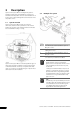
3.3.4 Uponor Actuators Uponor actuators are mounted on top of the valves of the manifolds When the thermostat senses that the temperature has fallen below the setpoint, the controller sends a signal to the actuator to open the valve. The indicator window on the actuator turns bright. When the thermostat senses that the temperature has risen above the setpoint, the controller sends a signal to the actuator to close the valve. The indicator window on the actuator turns dark.
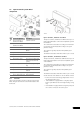
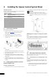
4 Installing the Uponor Control System Wired Installation procedure 2. Check that the connectors and switches are easily accessible. Uponor recommends that you follow the steps described below to achieve the best possible installation: CAUTION The Uponor Controllers C-33 and C-35 must be mounted horizontally. There is a risk for overheating if a controller is mounted vertically or on a horizontal surface. Section Description 4.1 Preparing the installation 4.
2. Press, without turning, with a thin screwdriver, on the white button of the quick connector. The controller senses automatically where the thermostats and the actuators are connected, this is called auto linking. 3. Insert a wire in the quick connector. Auto linking rules 4. Remove the screwdriver. In order to make the auto linking of the controller to work correctly, the following restrictions apply: 5.
4.3.3 Connecting thermostats and actuators to Uponor Controller C-33 Uponor Controller C-33 can only be used for heating. One to six thermostats and one to eight actuators can be connected to this controller. To connect the first thermostat with actuators to the controller, do this: Pos. Label Heating 4 Timer control zone 2 No cooling for this room Z2 Cooling NOTE! The two wires from the thermostat are non-polarized. Explanations to the different controller functions 1.
See section 4.4.4 Uponor Controller C-35 with four thermostats and timer for a connection example. 4.3.6 4. Open the lower lid (A) of the 230V compartment in the controller and fix it to the latch (B)on the upper part of the lid. Connecting a heating–cooling switch If the installation is equipped with a cooling unit, the Uponor Control System Wired can be run through a heating–cooling switch.
4. Open the lower lid (A) of the 230V compartment in the controller and fix it to the latch (B)on the upper part of the lid. • Thermostat #06 controls the actuator on channel 06 NOTE! The timer is not available for the 6-channel controller. NOTE! The economy mode (ECO) is not available for the 6channel controller. The installation will work in a standard way with the thermostats regulating each room according to their set temperatures. See also the wiring diagram on the foldout page. 5.
4.4.4 Uponor Controller C-35 with four thermostats and timer A connection example of Uponor Controller C-35 using four thermostats is shown in the figure below. NOTE! When connecting thermostats and actuators to the Uponor Controller, the auto-linking rules must always be followed strictly. See section 4.3.2 Auto linking, page 11 Any disregard to follow the auto linking rules will result in erroneous function of the Uponor Controller. 4.4.
Cooling mode • Thermostat #01 is connected to the (Common terminal) and Z1 connectors. The cooling will switch between comfort and economy mode according to timing pattern Z1. • Thermostat #03 is connected to the (Common terminal) and Z2 (cooling off) connectors. In cooling mode no cooling will be applied in this room. • Thermostats #05 and #12 are connected to the (Common terminal) and connectors (No timer control). Cooling is generated in comfort mode constantly.
4.5 Connecting the controller to AC power To conclude the installation of the controller: 1. Check that all wiring is complete and correct: • • • • • Thermostats Actuators Timer Heating–cooling switch Circulation pump 2. Ensure that the 230 V AC compartment of the controller is closed and the fixing screw is tightened. 3. Connect the power cable to a 230 V AC wall socket.
5 Installing thermostats The following thermostats can be connected to Uponor Control System Wired: • • • • • • Uponor Digital Thermostat T-36 Wired Uponor Programmable Digital Thermostat T-38 Wired Uponor Thermostat Flush T-34 Wired: Uponor Thermostat T-35 Wired: Uponor Thermostat T-37 Wired: Uponor Thermostat Public T-33 Wired: Analog thermostats • Uponor Thermostats T-34 and T-35: The temperature is adjusted with the dial.
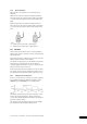
5.2.3 Connecting thermostat to controller To connect the thermostat to the controller: 1. Insert the two wires of the thermostat cable into the connector terminals labelled 1 and 2. 2. Tighten the screws fixing the wires in the terminal block. 2. At the back of the thermostat, gently push the three guides (two indicated in the figure below) to separate the electronics part from the mounting frame. Connecting the cable to the controller is described in section 4.
5.4.3 Connecting thermostats to controller To connect the thermostat to the controller: 1. Insert the two wires of the thermostat cable into the connector labelled POWER. Connecting the cable to the controller is described in section 4.3 Connecting components to controller, page 10. 2. Tighten the screws fixing the wires in the connector. 5.
When the maximum temperature setting is used, the frost protection is also active. This means that the floor temperature will never fall below +5 °C. To set the floor sensor potentiometer: 1. Use a cross-headed screwdriver to set the potentiometer. See figure below. 5.4.4 Connecting optional floor sensor Uponor Thermostats T-33 and T-37 allow a floor sensor to be fitted to the system. The temperatures thus measured ensure a more efficient management of the system. Wiring the floor sensor 1.
6 Installing Uponor Timer I-36 for C-35 Uponor Timer I-36 for C-35 is a digital timer with three buttons on the front to adjust various timing functions. For instructions how to operate the thermostats, see section 9 Operating digital thermostats, page 26. 6.1 Opening Uponor Timer I-36 To open Uponor Timer I-36: 1. Gently press the tab at the bottom of the thermostat housing. 2. Lift off the top part from the mounting frame. Connecting the cable to the controller is described in section 4.
7 Finishing installation Make a complete check up of the installation: 1. Check that the thermostats are working correctly. Turn thermostat setpoints to maximum to obtain a heating demand and make sure that the actuators are running. 2. Reset the thermostats to the defined operating settings. 3. Close the covers of the controller and the thermostats. 4. Fill in the “Installation report” on the centre pages of booklet. 5. Give the manual and all information about the system to the user.
8 Operating Uponor Control System Wired The Uponor Control System Wired controls the floor heating/ cooling installation according to customer needs. Temperatures are adjusted with thermostats located in each room. 8.1 Principle of operation As soon as the temperature measured at a thermostat is lower (heating mode) or higher (cooling mode) than the setpoint temperature, it sends this information to the controller, which opens the actuators for this room.
Pos. Description A Minimum temperature setpoint stopper B Maximum temperature setpoint stopper C Notch in the thermostat housing for setting the stoppers in the selected stopping positions (T-35 and T-37 only) 1. Carefully remove the dial using a small, flat-bladed screwdriver. 2. Set the minimum temperature limit with the blue stopper (A). 3. Set the maximum temperature limit with the red stopper (B).
9 Operating digital thermostats The digital thermostats T-36 and T-38 have a screen with a number of symbols for displaying different messages. Pos. Icon Description B Manual override. For example forced comfort or economy mode. Below the screen there are three buttons for operating the thermostats. Also used as a warning when defining the Min cooling temperaure in RFT mode. Heating mode Cooling mode Standby mode Holiday mode Used with empty house icon, see pos. F below. Lock mode.
Pos. Icon Description H Heating/Cooling demand • I 0 waves are shown if manual balancing is selected and the heating or cooling demand is off • 4 waves are shown if manual balancing is selected and the heating or cooling demand is on • 0 to 3 waves alternating sequentially if autobalancing is selected OK indicator. Confirms an activated function. 9.
9.5 Parameter and mode settings menu To enter the parameter and mode settings menu: 1. Press and hold the OK button for three seconds to enter the settings menu. • • T-38: The first menu, CLK (clock), is displayed T-36: The first menu, MOD (mode), is displayed The screen displays TME (time) and four digits designating the time are blinking. 11. Press the + and - buttons to change the setting: • Press once and the time setting increments with a 1 minute step.
• Monday till Sunday 5. Press OK to confirm the setting. The digital clock starts flashing. 6. Press and hold the OK key for 3 seconds to select the default schedule. The diagram below shows the default schedule for Monday till Friday or Monday till Saturday programming groups. 12. Press the OK key to change between comfort and economy mode at the desired time. Continue to the next comfort/economy changeover with the + button. Up to 5 changes in 24 hours are permitted. 13.
4. (Heating mode only) The symbol (heating mode) and MAX is displayed (maximum floor temperature limitation). 4.1. Press OK to display the limitation temperature. 4.2. Press the + and - buttons to change the setting. Default setting: 26 °C Setting range: 20 – 45 °C 4.3. Press OK to confirm the setting. 5. (Heating and cooling modes) The heating or cooling icon and MIN is displayed (low floor temperature limitation). 5.1. Press OK to display the limitation temperature. 5.2.
Exiting standby mode 1. Press and hold OK for three seconds. The thermostat name and software version are displayed for two seconds. Then the thermostat enters run mode. 9.15 Lock mode The three operating buttons can be locked to prevent unintentional use. Entering lock mode 1. Press and hold the + and - buttons simultaneuously for three seconds. The lock icon appears. Other displayed information remains and the thermostat operates as set-up. Exiting lock mode 1.
9.16 Menu trees The following sections show the menu trees for Uponor Thermostats T-36 and T-38 9.16.1 Uponor Thermostat T-36 Run mode, see section 9.4, page 27 Regulation choices, see section, see section 9.9, page 29 Room sensor regulation, see section 9.9, page 29 Room sensor regulation with floor sensor limitation, see section 9.9, page 29 Maximum floor temperature limitation, see section 9.9, page 29 Minimum floor temperature limitation, see section 9.
10 Operating Uponor Timer I-36 Uponor Timer I-36 has a screen with a number of icons and symbols for displaying messages. Pos. Icon Description B Manual override. For example forced comfort or economy mode. Below the screen there are three buttons for operating Uponor Timer I-36. Standby mode Holiday mode Used with empty house icon, see pos. F below. Lock mode. The three navigation buttons below the screen are locked.
10.2 Operating buttons The following three buttons are used to operate the Uponor Timer I-36: Button Description The OK button is used to: • • • Enter and exit the settings menu Confirm a setting Select comfort or economy mode • • • Zone Z1 is in economy mode Today is Tuesday Time is 13:20 Changing zone to be displayed To change the zone to be displayed: 1. Press the + or - button. The screen changes to display the other zone, that is, from zone Z1 to Z2 or the other way around.
The screen displays CLK (clock). The group of days flashes (day numbers with frames). 2. Press OK to enter the clock menu. The screen displays YR (year) and four digits designating the year are blinking. 3. Press the + and - buttons to change the setting. 4. Press OK to confirm the setting. The screen displays MTH (month) and two digits designating the month are blinking. 5. Press the + and - buttons to change the setting. 6. Press OK to confirm the setting.
3. Press OK to confirm the setting. The screen enters run mode. The timer starts to countdown the days when holiday mode is active. 11. Press the + and - buttons to modify the default clock setting: • Press once and the time setting increments with a 1 minute step. • Press continuously and the time setting increments with 1 minute steps, after a few seconds increments are made with 10 minute steps and then 1 hour steps. • Set the clock to the time for the first comfort/economy changeover. 12.
10.11 Menu tree The structure below illustrates the menu tree of Uponor Timer I-36. Run mode, see section 10.4, page 34 Clock settings, see section, see section 10.6, page 34 Year, see section, see section 10.6, page 34 Month, see section, see section 10.6, page 34 Day, see section, see section 10.6, page 34 Time, see section, see section 10.6, page 34 Summer-winter time, see section, 10.6, page 34 Programming mode, see section 10.7, page 35 Zone 1, see section 10.
11 Maintenance The maintenance of the Uponor Control System Wired includes the following: • • • Manual preventive maintenance Automatic preventive maintenance Corrective maintenance 11.1 Manual preventive maintenance The Uponor Control System Wired requires no preventive maintenance except cleaning: 1. Use a dry soft cloth to clean the Control System and all its components. Stop! Do not use any detergents to clean the Uponor System components. 11.
Problem Indication Probable cause Room too cold in heating The thermostat does not switch on The thermostat is connected on a mode or off with heating or cooling bad channel demand or The indicator window on the The actuator does not open Room too warm in actuator does not turn white cooling mode Check the thermostat setpoint Thermostat setting too low Solution 1. Check Installation report. 2. Check the wiring. 1. Replace the actuator. 2.
Problem Indication The system does not start The power indicator in the controller is off Probable cause Solution There is no AC power in the controller 1. Check that the controller is connected to AC power. 2. Check the wiring in the 230 V compartment. 3. Check that there is 230 V AC power in the wall socket. There is 230 V AC power in the wall Faulty power cable socket but not in 230 V compartment 1. Replace power cable and plug.
12 Technical data Controller Thermostats and Timer • • CE marking: • • • • • • • • Power supply: 230 V AC +10/-15 %, 50 Hz Operating temperature: 0 °C to +55 °C • < 2 W without any charge 230 V AC +10 %/-15 % • < 250 VA Heating–cooling and dew-point inputs: Only dry contact • Actuator outputs: 24 V DC ±5 %, 436 mA maximum per output 1 and 2 Dew-point sensor module output: 24 V DC ±5 %, 40 mA maximum • • • T-33, T-35, T-37: 0 °C to 50 °C T-34, T-36, T-38, I-36: 0 °C to 40 °C T-33, T-35, T-
Uponor Controller C-35 layout Pos. Description Pos.
Uponor Controller C-33 layout Pos. Description Pos.
Installation report Controller No.
UPONOR CONTROL SYSTEM WIRED - INSTALLATION AND OPERATION MANUAL 45
Uponor Housing Solutions Ltd. Snapethorpe House Rugby Road, Lutterworth Leicestershire LE17 4HN Tel. +44 1455 550 355 Fax +44 1455 550 366 www.uponorhousingsolutions.co.uk Uponor reserves the right to change specifications without prior notice, in keeping with our policy of continuous improvement and development.