
User Manual


06
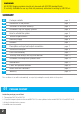
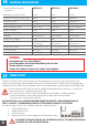
TECHNICAL SPECIFICATIONS
Weight without cylinders and battery
Fog emission in a single shoot (max density)
Total emission capacity
Cyliders capacity
Work time without main power
Average Consumption
Max power on heating system
Heating time
Average power consumption
Maximum consume at 12V
Average batteries lifetime
Door anti tampering
Anti-tear off or anti-shift
10 Kg
200 m
3
800 m
3
1 x 400 ml
about 2 hours
250 W
300 W
about 50 minutes
40 W
230 mA after shooting
60 mA stand-by
12 months with 10 shoots
Micro switch
Accelerometer
11 Kg
200 m
3
1600 m
3
2 x 400 ml
about 2 hours
250 W
300 W
about 50 minutes
40 W
230 mA after shooting
60 mA stand-by
12 months with 10 shoots
Micro switch
Accelerometer
14,7 Kg
400/1200 m
3
1500/4500 m
3
2 x 500 ml
2 hours 30 minutes
250 W
300 W
about 90 minutes
45 W
230 mA after shooting
60 mA stand-by
12 months with 10 shoots
Micro switch
Accelerometer
* Industrial standard as from other
manufacturers
FAST 03 1C FAST 03 2C FAST 02 2C
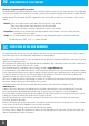
- Loosened ferrule can cause dropping
- Do not disconnect the machine immediately after the shot
- Change batteries every year
- Change the cylinder as soon as the “empty” signal appears
WARNING:
07
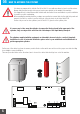
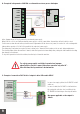
POWER SUPPLY
IF YOU NEED TO REPLACE THE FUSE, USE THE ONE WITH EXACTLY THE SAME SPECIFICATIONS.
IF IN DOUBT, ASK YOUR AUTHORIZED DEALER
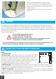
220V and 110V power source supplies energy only to the heating system. The electronic card and the motors of the
cylinders are supplied from the alarm system and batteries. The heating element is of 300W, at the very beginning power
consumption is about 250W and in some minutes it goes down reaching average consumption which is about 40W - 60W.
Do not use inverter or UPS unless you have the certainty that they generate a true sine wave, not a rebuilt one.
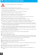
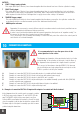
-The max current to be considered for the system is 4A
- The connection to the 230V and 110V electricity grid must be performed by a qualified technician.
- Connect the equipment to the electricity grid only after you have completed the installation.
- It is necessary to connect the ground terminal.
PLEASE NOTE THAT, AS ALL POWERED EQUIPMENT FROM THE ELECTRICITY GRID REQUIRING INSTALLA-
TION, IT IS SUBJECT TO COMPLIANCE WITH RULES OF THE COUNTRY IN WHICH IT IS INSTALLED
For section and types of wires, fuses, suitability of materials to installation sites etc..
1 Phase 220V and 110V
2 Neutral 220V and 110V
3 Ground connection
4 Ground connection for heat exchanger and cabinet (never disconect)
6