Mod. 1723 DS 1723-001A LBT 20298 KIT VIDEOCITOFONICO A 2 FILI MONO E BIFAMILIARE 7” VIVAVOCE A COLORI ONE- AND TWO-HOUSEHOLD KIT WITH PANEL AND COLOUR 7” HANDS-FREE MONITOR KIT VIDEO 2 FILS MONO/BI-FAMILLE 7” MAINS-LIBRES COULEUR KIT VIDEOINTERFÓNICO DE 2 HILOS MONO Y BIFAMILIAR 7” MANOS LIBRES COLOR 2-DRAHT-VIDEOSPRECHANLAGE-KIT FÜR EIN- UND ZWEIFAMILIENHÄUSER MIT FREISPRECHEINRICHTUNG UND 7“-FARBBILDSCHIRM KIT TWEEDRAADSE, HANDENVRIJE KLEUREN-VIDEO-INTERCOM VOOR EEN EN TWEE WONINGEN MET 7” DISPLAY Sch.
ITALIANO INDICE 1 2 3 4 5 6 7 8 9 10 11 12 13 DESCRIZIONE GENERALE............................................................................................................................... 3 COMPOSIZIONE DEL KIT ................................................................................................................................ 5 DISPOSITIVI ACCESSORI ................................................................................................................................
1 DESCRIZIONE GENERALE I kit videocitofonici Mod. NOTE2 sono caratterizzati dalla semplicità di installazione grazie all’utilizzo di 2 soli fili non polarizzati per l’interconnessione tra i vari dispositivi. La sua modularità permette di implementare svariate funzioni supplementari oltre a quelle base del sistema videocitofonico, offrendo soluzioni adeguate ad ogni esigenza. Le caratteristiche del sistema videocitofonico sono le seguenti: Sistema • Kit monofamiliare sch.
• Melodie di chiamata: 5 standard più 1 personalizzabile dall’utente; • Possibilità di attribuire melodie diverse a seconda della provenienza della chiamata (da pulsantiera, intercomunicante, chiamata al piano, segnalazione di allarme); • Dotato di: – Dispositivo di ripetizione della fonia per audiolesi (ILA); – N.
• Possibilità di esclusione del microfono; • Possibilità di visualizzare data e ora, con la funzione aggiuntiva di agenda; • Rilevazione di un allarme: – Segnalazione con led ed emissione di tono acustico sul videocitofono; – Ripetizione della segnalazione acustica su una sirena; – Attivazione di una telecamera per la ripresa delle immagini con registrazione automatica di un videomessaggio; • Attivazione di moduli radio Yokis da qualsiasi videocitofono; • Schedulazione delle attivazioni dei moduli radio Yok
Posto interno (B) Videocitofono “Master” 7” vivavoce Mod. VMODO (in quantità 1 nel kit sch. 1723/71, in quantità 2 nel kit sch. 1723/72) 1/2 B1 Staffa per fissaggio a parete (in quantità 1 nel kit sch. 1723/71, in quantità 2 nel kit sch. 1723/72) 1/2 B2 Viti per fissaggio a parete (ø 2,9 x 32 mm) (in quantità 4 nel kit sch. 1723/71, in quantità 8 nel kit sch. 1723/72) 4/8 B3 Tasselli per fissaggio a parete (ø 5 mm) (in quantità 4 nel kit sch. 1723/71, in quantità 8 nel kit sch.
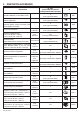
3 DISPOSITIVI ACCESSORI N° max (nell’ipotesi di massima configurazione dell’impianto) Descrizione ID Serratura elettrica (12 Vca Max 15 VA) - 2 (una ogni pulsantiera) OP1 Pulsante per azionamento serratura elettrica pedonale - 2 (uno ogni pulsantiera) OP2 Contatti del relè per l’attivazione apriporta passo carraio (corrente max commutabile 1A @ 30V) - 2 (uno ogni pulsantiera) OP3 Sensore porta aperta sch.
sch. 1723/69 Interfaccia TVCC Dispositivo video BALUN passivo ad 1 sch. canale 1092/300A sch. 1723/102 Kit chiavi Mifare 1 4 (uno per ogni telecamera connessa all’interfaccia TVCC) OP17 massimo 21 chiavi nell’impianto OP18 Telecamera compatta AHD DAY & NIGHT sch. con ottica fissa 3.6mm 1092/250A (max 4 se con kit sch. 1723/71, max 8 se con kit sch. 1723/72) 4/8 (una per videocitofono) Dispositivo video BALUN passivo ad 1 sch. canale 1092/300A 4/8 (uno ogni telecamera sch.
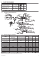
4 PARTI DI RICAMBIO Descrizione ID Alimentatore di sistema sch. 1723/20 C1 Induttanza audio video sch. 1723/112 C2 Distributore video sch. 1723/55 D 5 5.1 SCHEMI A BLOCCHI DI COLLEGAMENTO IMPIANTO MONOFAMILIARE OP1 OP5 B 2 OP2 OP21 Master OP7 2 2 2 2 2 OP3 OP4 2 2 OP8 2 2 OP20 2 C2 4 2 A1 OP22 OP19 2 2 OP6 OP5 2 Slave 2 OP22 4 2 C1 OP19 2 OP6 230 V~ OP5 2 Slave 2 2 2 OP22 4 OP19 230 V~ C4 2 OP6 OP5 Slave 2 C4 2 OP22 4 2 OP19 230 V~ 5.1.
5.2 IMPIANTO BIFAMILIARE 2 OP1 2 OP2 D 2 2 2 2 OP3 2 OP21 C2 A2 2 OP5 OP5 2 OP7 2 OP7 2 2 2 OP8 2 2 230 V~ B Master 1 B OP22 Master 2 OP22 2 OP19 2 OP19 OP5 2 Appartamento 0 (APT0) Slave OP22 2 OP6 OP19 OP5 2 OP5 OP6 OP5 2 OP22 2 OP6 OP19 Slave 4 2 2 2 2 OP5 C4 2 OP22 OP6 OP19 Slave 2 2 230 V~ OP5 2 OP6 OP19 4 2 2 OP22 2 Slave 230 V~ C4 OP19 4 2 2 OP22 2 Slave 4 2 2 OP22 OP19 Slave 4 4 2 230 V~ 2 230 V~ C4 5.2.
6 AVVERTENZE PER L’INSTALLATORE Leggere attentamente le avvertenze contenute nel presente documento in quanto forniscono importanti indicazioni riguardanti la sicurezza di installazione, uso e manutenzione. • I dispositivi facenti parte del kit dovranno essere destinati solo all’uso per il quale sono stati espressamente concepiti. Ogni altro uso è da considerarsi improprio. Il costruttore non può essere considerato responsabile per eventuali danni derivanti da usi impropri ed irragionevoli.
7 7.1 INSTALLAZIONE DEL VIDEOCITOFONO DESCRIZIONE DEI COMPONENTI Frontale: 1. Icona Allarme 2. Icona segnalazione presenza posta nella buca delle lettere (funzione LETTERBOX) 3. Icona presenza messaggi audio POST-IT 4. Display 7’’ 5. Icona che indica che il videocitofono ha la ripetizione di fonia per gli audiolesi (ILA) 6. Altoparlanti 7. Pulsante (touch) apriporta 8. Icona conferma ricezione comando Yokis 9. Pulsante di accensione ON/OFF 10. Pulsante (touch) “MUTE” 11.
7.2 MODALITÀ DI INSTALLAZIONE • Fissare la staffa alla parete utilizzando una scatola 503 e le viti in dotazione o una scatola Ø 60 mm con viti adeguate. • Programmare i dip-switch e collegare alle morsettiere i conduttori dell’impianto. • Agganciare il videocitofono alla staffa in corrispondenza dei 4 ganci posti sui lati. • Rimuovere la pellicola di protezione dal display. 150 cm(*) 150 cm(*) n. 2 M3,5 x 19 mm a corredo 2 Scatola Ø 60 mm Scatola 503 1 n.
7.4 DESCRIZIONE DEL CONNETTORE PER LA TELECAMERA ESTERNA / RELE’ 2 (OP20) È possibile connettere al videocitofono “Master” la telecamera esterna sch. 1092/250A per mezzo del cavetto (B7) fornito a corredo. N.
7.7.1 Associazione pulsante di chiamata a videocitofono Posizione dip-switch 1 Videocitofono associato al pulsante di chiamata 0 (superiore) 7.7.2 ON 1 2 3 4 5 6 7 8 Posizione dip-switch 1 Videocitofono associato al pulsante di chiamata 1 (inferiore) ON 1 2 3 4 5 6 7 8 Codice del videocitofono Qualora si desideri installare dei videocitofoni “Slave” è necessario impostare su ogni posto interno il relativo codice tramite i dip-switch 2 e 3.
8 INSTALLAZIONE DELL’ALIMENTATORE DI SISTEMA E DELL’INDUTTANZA AUDIO VIDEO L’alimentatore deve essere installato all’interno di un quadro elettrico oppure di un armadietto. 1 2 Installazione su barra DIN (6 moduli da 18 mm) Installazione ad appoggio parete Il modulo induttanza può essere fissato a parete tramite la staffa fornita a corredo oppure fissato su barra DIN (2 moduli da 18 mm). Il modulo induttanza deve essere installato nello stesso quadro elettrico dell’alimentatore. 8.1.
9 9.1 INSTALLAZIONE DELLA PULSANTIERA DESCRIZIONE DEI COMPONENTI Pulsantiera Mod. MIKRA2 con 1 tasto di chiamata (presente solo nel kit monofamiliare sch. 1723/71) Pulsantiera Mod. MIKRA2 con 2 tasti di chiamata (presente solo nel kit bifamiliare sch. 1723/72) Frontale: 1. Altoparlante 2. Led di illuminazione telecamera 3. Telecamera 4. Lettore transponder 5. Cartellino/i portanome 6. Segnalazioni led dedicate alla funzione DDA 7. Pulsante/i di chiamata 8. Microfono 9.
9.
9.3 DESCRIZIONE DEI MORSETTI Morsettiera sinistra SENegativo azionamento elettroserratura con scarica capacitiva SE+ Positivo azionamento elettroserratura con scarica capacitiva ] PA Ingresso per pulsante serratura elettrica pedonale SP Ingresso per sensore dedicato alla funzione STATO PORTA oppure LETTERBOX Morsettiera destra SP Ingresso per sensore dedicato alla funzione STATO PORTA oppure LETTERBOX ] ] 9.4 LINE Linea Bus N.O.
9.4.6 Impostazione del tipo di pulsantiera Posizione dip-switch 6 Posizione dip-switch 6 ON Pulsantiera monofamiliare ON Pulsantiera bifamiliare 1 2 3 4 5 6 7 8 9 10 9.4.7 1 2 3 4 5 6 7 8 9 10 Regolazione del tempo di attivazione dell’elettroserratura con scarica capacitiva Posizione dip-switch 7-8 0 secondi (impulso di 300ms) Posizione dip-switch 7-8 ON ON 3 secondi 1 2 3 4 5 6 7 8 9 10 1 2 3 4 5 6 7 8 9 10 ON ON 6 secondi 9 secondi 1 2 3 4 5 6 7 8 9 10 9.4.
In entrambi i casi, riduzione della portata in presenza di elementi metallici, attraversamento di muri o paratie. Trasmissione radio: il led del trasmettitore si accende solo nel caso in cui la trasmissione sia andata a buon fine. In caso di portata insufficiente, l’aggiunta di ricevitore intermedio consente di risolvere il problema. Fare riferimento al libretto istruzione dei trasmettitori Yokis. Frequenza radio: ..............................................................................................
ENGLISH CONTENTS 1 2 3 4 5 6 7 8 9 10 11 12 13 22 GENERAL DESCRIPTION ............................................................................................................................... 23 KIT COMPOSITION......................................................................................................................................... 25 ACCESSORY DEVICES ..................................................................................................................................
1 GENERAL DESCRIPTION The NOTE2 video door phone system is easy to install. Only two non-polarised wires are needed to interconnect all system devices. Modularity mean being able to implement various supplementary functions, in addition to the basic video door phone functions, offering solutions suited to all needs. The features of the video door phone system are: System • One-household kit ref. 1723/71: – Allows the use of two video door phones without any supplementary power supply.
• Possibility of directly connecting to the video door phone: – One local CCTV camera, ref. 1092/250A. – One floor call button (only on Master). – One external temperature sensor (ref. 1430/50). – One alarm contact (only on Master). • Possibility of connecting a supplementary ringer or wireless call repeater to each video door phone (French market only). • Possibility of changing the image viewing ratio from 4:3 to 16:9.
• Call and/or alarm divert to smartphone, with dedicated device. • Possibility of updating system firmware using the microSD card. 2 KIT COMPOSITION Panel (A) Description N Panel model MIKRA2 with 1 calling button (present only in kit ref. 1723/71) 1 A1 Panel model MIKRA2 with 2 calling buttons (present only in kit ref. 1723/72) 1 A2 Screws for fixing to wall (ø 3.5 x 32 mm) 4 A3 Anchor bolts for fastening to wall (ø 5 mm) 4 A4 Screwdriver insert (ø 2 mm) 1 A5 Grey name tag (qty.
Apartment station (B) Video door phone Mod. VMODO Master (qty. 1 in kit ref. 1723/71, qty. 2 in kit ref. 1723/72) 1/2 B1 Bracket for fixing to wall (qty. 1 in kit ref. 1723/71, qty. 2 in kit ref. 1723/72) 1/2 B2 Screws for fixing to wall (ø 2.9 x 32 mm) (qty. 4 in kit ref. 1723/71, qty. 8 in kit ref. 1723/72) 4/8 B3 Anchor bolts for fastening to wall (ø 5 mm) (qty. 4 in kit ref. 1723/71, qty. 8 in kit ref. 1723/72) 4/8 B4 Screws for fixing to flush-mounting box Mod. 503 (M3.5 x 19 mm) (qty.
3 ACCESSORY DEVICES Max. n. (maximum system configuration) Description ID Electric lock (12 Vac Max. 15 VA) - 2 (one for each panel) OP1 Button for pedestrian gate electric lock - 2 (one for each panel) OP2 Relay contacts for garage gate lock activation device (max. switching current 1 A @ 30 V) - 2 (one for each panel) OP3 Open door sensor Ref. 1033/701 2 (one for each panel) OP4 (*) Supplementary ringer (max. 4 with kit ref. 1723/71, max. 8 with kit ref. 1723/72) Ref.
Flush-mounting kit for video door phone 7” hands-free (max. 4 if with kit ref. 1723/71, max. 8 if with kit ref. 1723/72) Ref. 1723/60 4/8 CCTV interface Ref. 1723/69 1 4 BALUN passive one-channel video Ref. (one for each camera connected to the 1092/300A device CCTV interface) Mifare key kit Ref. 1723/102 maximum 21 keys in the system Compact AHD DAY & NIGHT camera with 3.6mm fixed lens Ref. 1092/250A (max. 4 if with kit ref. 1723/71, max. 8 if with kit ref.
4 SPARE PARTS Description ID System power supply unit Ref. 1723/20 C1 Audio video inductor Ref. 1723/112 C2 Video distributor Ref. 1723/55 D 5 CONNECTION BLOCK CHART 5.1 ONE-HOUSEHOLD SYSTEM OP1 OP5 B 2 OP2 OP21 Master OP7 2 2 2 2 2 OP3 OP4 2 2 OP8 2 2 OP20 2 C2 4 2 A1 OP22 OP19 2 2 OP6 OP5 2 Slave 2 OP22 4 2 C1 OP19 2 OP6 230 V~ OP5 Slave 2 2 2 2 OP22 4 OP19 230 V~ C4 2 OP6 OP5 Slave 2 C4 2 OP22 4 2 OP19 230 V~ 5.1.
5.
6 WARNINGS FOR INSTALLERS Read the notes in this manual carefully. This manual contains important information on safe installation, use and maintenance. • This devices in the kit must only be put to the use for which they were intended. All other use is improper. The manufacturer cannot be held responsible for damage deriving from improper, incorrect or unreasonable use. • Each part was designed to be compliant with the standards in force.
7 7.1 VIDEO DOOR PHONE INSTALLATION DESCRIPTION OF COMPONENTS Front panel: 1. Alarm icon 2. Mail in letterbox indication icon (LETTERBOX function) 3. POST-IT audio message presence icon 4. 7’’ display 5. Icon indicating that the video door phone is hearing-aid compatible (ILA) 6. Speakers 7. Door opening button (touch) 8. Yokis command reception confirmation icon 9. ON/OFF button 10. MUTE button (touch) 11. Audio on button (touch) Rear part: 12. Configuration dip-switch: 13. Jumpers 14.
7.2 Fix the bracket to the wall using a box 503 and the screws provided or a Ø 60 mm box with suitable screws. Program the dip-switches and connect the system wires to the terminal boards. Couple the video door phone to the bracket at the four hooks on the sides. Remove the protective film from the display. Box Ø 60 mm Box 503 150 cm 1 2 M3.5 x 19 mm provided 2 2.9 x 13 mm countersunk screws 2 150 cm • • • • INSTALLATION METHOD 1 2 3 7.
7.4 OUTDOOR CAMERA/RELAY 2 (OP20) CONNECTOR DESCRIPTION The outdoor camera ref. 1092/250A can be connected to the Master video door phone using the wire (B7) provided. Wire n.
7.7.1 Calling button to video door phone association Dip-switch 1 position Video door phone associated with calling button 0 (upper) 7.7.2 ON 1 2 3 4 5 6 7 8 Dip-switch 1 position Video door phone associated with calling button 1 (lower) ON 1 2 3 4 5 6 7 8 Video door phone code Set the respective code using the dip-switches 2 and 3 on each apartment station to install Slave video door phones.
8 SYSTEM POWER SUPPLY AND AUDIO VIDEO INDUCTOR INSTALLATION The power supply unit must be installed in the electric panel or a cabinet. 1 2 Installation on DIN bar (6 modules, 18 mm) Wall-mounted installation The electronic inductor module may be fixed to the wall by means of bracket supply in the kit or fixed to DIN bar (2 modules, 18 mm each). The electronic inductor module must be installed in the same electric panel as the power supply unit. 8.1.
9 9.1 CONTROL PANEL INSTALLATION DESCRIPTION OF COMPONENTS Panel Mod. MIKRA2 with 1 calling button (present only in one-household kit ref. 1723/71) Panel Mod. MIKRA2 with 2 calling buttons (present only in two-household kit ref. 1723/72) Front panel: 1. Speaker 2. Camera lighting LED 3. Camera 4. Transponder reader 5. Name tag(s) 6. Signalling LEDs dedicated to the DDA function 7. Calling button(s) 8. Microphone 9. Front closing screw Inside: 10. Configuration dip-switch: 11. Terminal boards 12.
9.2 Install the panel at the indicated heights checking that the caller is framed by the camera. Connect the wires to the terminal boards. Fit the name tags on the front. Program the device. If necessary, adjust the speaker volume. Close the metal lid of the panel. Remove the protective films.
9.3 DESCRIPTION OF TERMINALS Left terminal board SEElectrical lock with capacitance discharge actuation negative SE+ Electrical lock with capacitance discharge actuation positive ] PA Input for pedestrian gate electric lock button SP Input for DOOR STATE or LETTERBOX function sensor Right terminal board SP Input for DOOR STATE or LETTERBOX function sensor ] ] 9.4 LINE Bus line N.O.
9.4.6 Panel type setting Dip-switch 6 position Dip-switch 6 position ON One-household panel ON Two-household panel 1 2 3 4 5 6 7 8 9 10 9.4.7 1 2 3 4 5 6 7 8 9 10 Lock activation time adjustment with capacitance discharge Dip-switch 7-8 position Dip-switch 7-8 position ON ON 3 seconds 0 seconds (300ms pulse) 1 2 3 4 5 6 7 8 9 10 1 2 3 4 5 6 7 8 9 10 ON ON 6 seconds 9 seconds 1 2 3 4 5 6 7 8 9 10 9.4.8 1 2 3 4 5 6 7 8 9 10 Default settings ON One-household kit ref.
Radio transmission: the transmitter LED lights up only if the radio transmission was successful. Adding an intermediate receiver will solve the problem of insufficient range. Refer to the Yokis transmitter instruction booklet for more information. Radio frequency: ......................................................................................................................................... 2.4 GHz Relay output 1 (OP5) ................................................................................
FRANÇAIS SOMMAIRE 1 2 3 4 5 6 7 8 9 10 11 12 13 42 DESCRIPTION GENERALE............................................................................................................................. 43 COMPOSITION DU KIT .................................................................................................................................. 45 ACCESSOIRES ..............................................................................................................................................
1 DESCRIPTION GENERALE Les kits vidéo NOTE 2 sont caractérisés par une grande simplicité d’installation, grâce à l’utilisation de seulement 2 fils non polarisés pour l’interconnexion de tous les dispositifs du système. Leur modularité permet d’ajouter d’autres fonctions, en plus de celles de base du système de vidéoportier, en offrant ainsi des solutions ciblées pour chaque exigence. Le kit vidéo possède les caractéristiques suivantes : Système • Kit mono-famille réf.
• • • • • • • • • • • • • • • • • Possibilité d’attribuer des sonneries différentes en fonction de la provenance de l’appel (plaque, intercom, appel palier, alarme) ; Avec : – Dispositif de répétition de la phonie pour malentendants (boucle magnétique) ; – Deux sorties configurables avec des relais à contact sec pour l‘activation des commandes auxiliaires ; – Rétro-éclairage des boutons avec diodes rouge ou verte ; Possibilité de brancher directement au moniteur : – Une caméra de surveillance locale réf
• Possibilité d’afficher la date et l’heure, avec fonction agenda supplémentaire ; • Détection d’une alarme : – Signalisation par diodes et émission d’une tonalité sur le moniteur ; – Répétition du signal sonore par une sirène ; – Activation d’une caméra pour filmer les images, avec enregistrement automatique d’une vidéo ; • Activation de modules radio Yokis depuis n’importe quel moniteur ; • Programmation des activations des modules radio Yokis une ou plusieurs fois par semaine ; • Transfert de l’appel et/
Moniteur (B) Alimentation (C) (D) 46 Moniteur modèle VMODO “Maître” (1 dans le kit réf. 1723/71, 2 dans le kit réf. 1723/72) 1/2 B1 Etrier de fixation murale (1 dans le kit réf. 1723/71, 2 dans le kit réf. 1723/72) 1/2 B2 Vis de fixation murale (ø2,9 x 32mm) (4 dans le kit réf. 1723/71, 8 dans le kit réf. 1723/72) 4/8 B3 Chevilles de fixation murale (ø5mm) (4 dans le kit réf. 1723/71, 8 dans le kit réf. 1723/72) 4/8 B4 Vis de fixation sur boîtier encastrable Mod.
3 ACCESSOIRES N.bre maximum (en cas de configuration maximale de l’installation) Description ID Serrure électrique (12 Vca Maxi 15 VA) - 2 (une par plaque) OP1 Bouton de commande de la serrure électrique pour piétons - 2 (une par plaque) OP2 Contacts du relais d’activation ouvre-porte d’accès véhicules (courant maxi commutable 1 A @ 30 V) - 2 (une par plaque) OP3 Capteur de porte ouverte réf. 1033/701 2 (une par plaque) OP4 (*) Sonnerie supplémentaire (max. 4 avec le kit réf.
Interface 4 caméras de surveillance réf. 1723/69 1 Dispositif vidéo BALUN passif 1 voie réf. 1092/300A 4 (un pour chaque caméra branchée sur l’interface 1723/69) réf. 1723/102 21 clés maxi dans l’installation. Kit de clés de proximité Mifare Caméra compacte AHD JOUR & NUIT avec réf. optique fixe 3,6mm (max. 4 avec le kit réf. 1723/71, 1092/250A (max. 8 avec le kit réf. 1723/72) OP17 OP18 4/8 (une par moniteur) OP19 (#) réf. 1092/300A 4/8 (un par caméra réf.
4 PIECES DETACHEES Description ID Alimentation système réf. 1723/20 C1 Inductance audio/vidéo réf. 1723/112 C2 Distributeur vidéo réf. 1723/55 D 5 SYNOPTIQUES DE CONNEXION 5.1 INSTALLATION MONO-FAMILLE OP1 OP5 B 2 OP2 OP21 Maître OP7 2 2 2 2 2 OP3 OP4 2 2 OP8 2 2 OP20 2 C2 4 2 A1 OP22 OP19 2 2 OP6 OP5 2 Esclave 2 OP22 4 2 C1 OP19 2 OP6 230 V~ OP5 Esclave 2 2 2 2 OP22 4 OP19 230 V~ C4 2 OP6 Esclave 2 230 V~ 5.1.
5.
6 AVERTISSEMENTS POUR L’INSTALLATEUR Lire attentivement les instructions contenues dans le présent document, car elles fournissent d’importantes indications pour la sécurité d’installation, d’utilisation et d’entretien. • Les dispositifs inclus dans le kit doivent être exclusivement destinés à l’utilisation pour laquelle ils ont été expressément conçus. Toute autre utilisation doit être considérée comme étant inappropriée.
7 7.1 INSTALLATION DU MONITEUR DESCRIPTION DES COMPOSANTS Façade: 1. Icône Alarme 2. Icône de présence de courrier dans la boîte aux lettres (fonction LETTERBOX) 3. Icône de présence de messages audio POST-IT 4. Afficheur 7’’ 5. Icône indiquant que le moniteur est doté de répétition de phonie pour les malentendants (boucle magnétique) 6. Haut-parleurs 7. Touche ouvre-porte 8. Icône de confirmation de réception commande Yokis 9. Bouton marche/arrêt (ON/OFF) 10. Touche “MUTE” 11.
7.2 MODALITES D’INSTALLATION • Fixer l’étrier à la paroi en utilisant un boîtier 503 et les vis livrées de série, ou bien un boîtier Ø 60 mm avec des vis appropriées. • Programmer les commutateurs et brancher les conducteurs de l’installation sur les borniers. • Accrocher le moniteur à l’étrier, au niveau des quatre crochets latéraux. • Retirer le film de protection de l’afficheur. 150 cm(*) 150 cm(*) n.2 M3,5 x 19 mm de série 2 Boîtier Ø 60 mm Boîtier 503 1 n.
7.4 DESCRIPTION DU CONNECTEUR POUR LA CAMERA EXTERNE / RELAIS 2 (OP20) La caméra externe réf. 1092/250A peut être branchée sur le moniteur Maître à l’aide du câble (B7), livré de série. N.
7.7.1 Association bouton d’appel/ moniteur Position du commutateur 1 Moniteur associé au bouton d’appel 0 (en haut) 7.7.2 ON 1 2 3 4 5 6 7 8 Position du commutateur 1 Moniteur associé au bouton d’appel 1 (en bas) ON 1 2 3 4 5 6 7 8 Code du moniteur En cas d’installation de moniteurs Esclaves, il est nécessaire de configurer le code correspondant sur chaque poste interne à l’aide des commutateurs 2 et 3.
8 INSTALLATION DE L’ALIMENTATION SYSTEME ET DE L’INDUCTANCE AUDIO/VIDÉO L’alimentation doit être installée à l’intérieur d’un tableau ou d’une armoire électrique. 1 2 Installation sur barre DIN (6 modules de 18 mm) Installation murale en saillie Le module d’inductance peut être fixé à la paroi à l’aide de l’étrier livré de série ou bien sur barre DIN (2 modules de 18 mm). Le module d’inductance doit être installé dans la même armoire électrique que celle de l’alimentation. 8.1.
9 9.1 INSTALLATION DE LA PLAQUE DE RUE DESCRIPTION DES COMPOSANTS Plaque modèle MIKRA2 avec 1 touche d’appel (uniquement dans le kit mono-famille réf. 1723/71) Plaque modèle MIKRA2 avec 2 touches d’appel (uniquement dans le kit bi-famille réf. 1723/72) Façade: 1. Haut-parleur 2. Diode d’éclairage caméra 3. Caméra 4. Lecteur de badge 5. Etiquette(s) de nom 6. Diodes de signalisation pour la fonction signalisation 7. Bouton(s) d’appel 8. Microphone 9. Vis de fermeture façade Partie intérieure : 10.
9.2 Installer la plaque à la hauteur indiquée. Brancher les fils sur les borniers. Installer les étiquettes des noms sur la façade. Effectuer les programmations. Si nécessaire, régler le niveau phonique du haut-parleur. Refermer la plaque à l’aide de son couvercle métallique.
9.3 DESCRIPTION DES BORNES Bornier gauche SENégatif d’actionnement de la serrure électrique à décharge capacitive SE+ Positif d’actionnement de la serrure électrique à décharge capacitive ] PA Entrée pour bouton serrure électrique pour piétons SP Entrée pour capteur réservé à la fonction ETAT PORTE ou LETTERBOX (BOITE AUX LETTRES) Bornier droit SP ] ] 9.4 Entrée pour capteur réservé à la fonction ETAT PORTE ou LETTERBOX (BOITE AUX LETTRES) LINE Ligne Bus N.O.
9.4.6 Configuration du type de plaque Position du commutateur 6 Position du commutateur 6 ON ON Plaque bi-famille Plaque mono-famille 1 2 3 4 5 6 7 8 9 10 9.4.7 1 2 3 4 5 6 7 8 9 10 Réglage de la durée d’activation de la serrure électrique à décharge capacitive Position du commutateur 7-8 Position du commutateur 7-8 ON ON 3s 0 s (impulsion de 300ms) 1 2 3 4 5 6 7 8 9 10 1 2 3 4 5 6 7 8 9 10 ON 6s ON 9s 1 2 3 4 5 6 7 8 9 10 9.4.
Portée radio : • à l’intérieur d’une habitation de 100m² avec traversée perpendiculaire d’un mur porteur ou d’une dalle ; • 250m à l’air libre Dans les deux cas, réduction de la portée en présence d’éléments métalliques, de traversée de murs ou de cloisons. Transmission radio : la diode de l’émetteur ne s’allume que si la transmission a abouti. En cas de portée insuffisante, l’ajout d’un récepteur intermédiaire permet de résoudre le problème. Se reporter à la notice d’instructions des émetteurs Yokis.
ESPAÑOL ÍNDICE 1 2 3 4 5 6 7 8 9 10 11 12 13 62 DESCRIPCIÓN GENERAL .............................................................................................................................. 63 COMPOSICIÓN DEL KIT ................................................................................................................................ 65 DISPOSITIVOS ACCESORIOS .......................................................................................................................
1 DESCRIPCIÓN GENERAL Los kits videointerfónicos Mod. NOTE2 se caracterizan por la facilidad de instalación gracias al uso de sólo 2 cables no polarizados para la interconexión entre los diversos dispositivos. Su carácter modular permite complementar numerosas funciones adicionales, además de las básicas del sistema videointerfónico, ofreciendo soluciones para todas las exigencias. Las características del sistema videointerfónico son las siguientes: Sistema • Kit monofamiliar ref.
• Posibilidad de asignar distintas melodías según la procedencia de la llamada (de teclado, intercomunicante, llamada al piso, indicación de alarma); • Equipado con: – Dispositivo de repetición de la fonía para hipoacúsicos (ILA); – Nº 2 salidas configurables de relé con contactos limpios para la activación de mandos auxiliares; – Iluminación en la cara posterior de los pulsadores táctiles con led rojo o verde • Posibilidad de conectar directamente al videointerfono: – Una cámara TVCC local ref.
• Posibilidad de ver la fecha y la hora, con la función adicional de agenda; • Detección de una alarma: – Indicación con led y emisión de tono acústico en el videointerfono; – Repetición de la indicación acústica en una sirena; – Activación de una cámara para captar las imágenes con grabación automática de un mensaje vídeo; • Activación de módulos radio Yokis desde cualquier videointerfono; • Programación de las activaciones de los módulos radio Yokis en una o más ocasiones semanales; • Desviación de la lla
Aparato interior (B) Videointerfono Mod. VMODO “Master” (cantidad: 1 en el kit ref. 1723/71, cantidad: 2 en el kit ref. 1723/72) 1/2 B1 Soporte para la fijación de pared (cantidad: 1 en el kit ref. 1723/71, cantidad: 2 en el kit ref. 1723/72) 1/2 B2 Tornillos para la fijación en la pared (ø 2,9 x 32 mm) (cantidad: 4 en el kit ref. 1723/71, cantidad: 8 en el kit ref. 1723/72) 4/8 B3 Tacos de fijación en la pared (ø 5 mm) (cantidad: 4 en el kit ref. 1723/71, cantidad: 8 en el kit ref.
3 DISPOSITIVOS ACCESORIOS N° máx. (considerando la configuración máxima del sistema) Descripción ID Cerradura eléctrica (12 Vca Máx. 15 VA) - 2 (una por teclado) OP1 Pulsador de accionamiento de la cerradura eléctrica para peatones - 2 (uno por teclado) OP2 Contactos del relé para la activación de la apertura de la puerta del pasaje para vehículos (máx. corriente conmutable 1 A @ 30 V) - 2 (uno por teclado) OP3 Sensor de puerta abierta ref.
Kit para empotrar para videointerfono 7” manos libres (máx. 4 con kit ref. 1723/71, máx. 8 con kit ref. 1723/72) ref. 1723/60 4/8 Interfaz TVCC ref. 1723/69 1 ref. 1092/300A 4 (uno por cada cámara conectada a la interfaz TVCC) ref. 1723/102 un máximo de 21 llaves en el sistema Dispositivo vídeo BALUN pasivo de 1 canal Kit de llaves Mifare Cámara compacta AHD DAY & NIGHT con ref. óptica fija 3,6 mm (máx. 4 con kit ref. 1723/71, 1092/250A máx. 8 con kit ref.
4 PIEZAS DE REPUESTO Descripción ID Alimentador del sistema ref. 1723/20 C1 Inductancia audio vídeo ref. 1723/112 C2 Distribuidor vídeo ref. 1723/55 D 5 DIAGRAMA DE BLOQUES DE CONEXIÓN 5.1 SISTEMA MONOFAMILIAR OP1 OP5 B 2 OP2 OP21 Master OP7 2 2 2 2 2 OP3 OP4 2 2 OP8 2 2 OP20 2 C2 4 2 A1 OP22 OP19 2 2 OP6 OP5 2 Slave 2 OP22 4 2 C1 OP19 2 OP6 230 V~ OP5 Slave 2 2 2 2 OP22 4 OP19 230 V~ C4 2 OP6 OP5 Slave 2 C4 2 OP22 4 2 OP19 230 V~ 5.1.
5.2 SISTEMA BIFAMILIAR 2 OP1 2 OP2 D 2 2 2 2 OP3 2 OP21 C2 A2 2 OP5 OP5 2 OP7 2 OP7 2 2 2 OP8 2 2 230 V~ B Master 1 B OP22 Master 2 OP22 2 OP19 2 OP19 OP5 2 Apartamento 0 (APT0) Slave OP22 2 OP6 OP19 OP19 OP6 OP5 2 OP22 2 OP6 OP19 Slave 2 4 2 2 2 2 2 230 V~ OP5 OP6 OP5 C4 2 OP22 OP6 OP19 Slave 2 OP22 OP19 Slave 4 2 OP19 4 2 2 OP22 Slave 230 V~ 2 OP22 2 OP5 C4 2 4 2 2 4 2 230 V~ 2 230 V~ C4 5.2.
6 ADVERTENCIAS PARA EL INSTALADOR Leer atentamente las advertencias contenidas en este documento, ya que brindan indicaciones importantes referidas a la seguridad de instalación, uso y mantenimiento. • Los dispositivos que forman parte del kit se deben destinar sólo al uso para el que han sido expresamente diseñados. Cualquier otro uso se debe considerar impropio. El fabricante no se considera responsable de posibles daños que deriven de un uso impropio o desatinado.
7 7.1 INSTALACIÓN DEL VIDEOINTERFONO DESCRIPCIÓN DE LOS COMPONENTES Delantero: 1. Icono de alarma 2. Icono de indicación de presencia de correo en el buzón (función LETTERBOX) 3. Icono de presencia de mensajes audio POST-IT 4. Pantalla 7” 5. Icono que indica que el videointerfono tiene la repetición de fonía para hipoacúsicos (ILA) 6. Altavoces 7. Pulsador (táctil) de apertura de la puerta 8. Icono de confirmación de recepción de mando Yokis 9. Pulsador de encendido ON / OFF 10.
7.2 MODO DE INSTALACIÓN • Fijar el soporte en la pared utilizando una caja 503 y los tornillos entregados con el equipo, o una caja Ø 60 con tornillos apropiados. • Programar los interruptores dip y conectar en los tableros de bornes los conductores del sistema. • Enganchar el videointerfono en el soporte, en los 4 ganchos presentes sobre los lados. • Retirar la película de protección de la pantalla.
7.4 DESCRIPCIÓN DEL CONECTOR PARA LA CÁMARA EXTERNA / RELÉ 2 (OP20) Es posible conectar al videointerfono “Master” la cámara externa ref. 1092/250A mediante el cable (B7) entregado con el equipo. N.
7.7.1 Asociación de un pulsador de llamada al videointerfono Posición interruptor dip 1 Videointerfono asociado al pulsador de llamada 0 (superior) 7.7.2 ON 1 2 3 4 5 6 7 8 Posición interruptor dip 1 Videointerfono asociado al pulsador de llamada 1 (inferior) ON 1 2 3 4 5 6 7 8 Código del videointerfono Para instalar videointerfonos “Slave” es necesario configurar en cada aparato interior el código correspondiente a través de los interruptores dip 2 y 3.
8 INSTALACIÓN DEL ALIMENTADOR DEL SISTEMA Y DE LA INDUCTANCIA AUDIO VÍDEO El alimentador se debe instalar dentro de un tablero eléctrico o de un armario. 1 2 Instalación en barra DIN (6 módulos de 18 mm) Instalación con apoyo de pared El módulo inductancia se puede fijar en la pared utilizando el soporte entregado con el equipo y se puede fijar en barra DIN (2 módulos de 18 mm). El módulo inductancia se debe instalar en el mismo tablero eléctrico que el alimentador. 8.1.
9 9.1 INSTALACIÓN DEL TECLADO DESCRIPCIÓN DE LOS COMPONENTES Teclado Mod. MIKRA2 con 1 pulsador de llamada (presente sólo en el kit monofamiliar ref. 1723/71) Teclado Mod. MIKRA2 con 2 pulsadores de llamada (presente sólo en el kit bifamiliar ref. 1723/72) Delantero: 1. Altavoz 2. Led de iluminación cámara 3. Cámara 4. Lector transpondedor 5. Tarjetero/s para nombres 6. Indicaciones led específicas de la función DDA 7. Pulsador/pulsadores de llamada 8. Micrófono 9.
9.
9.3 DESCRIPCIÓN DE LOS BORNES Tablero de bornes izquierdo SENegativo de accionamiento cerradura eléctrica con descarga capacitiva SE+ Positivo de accionamiento cerradura eléctrica con descarga capacitiva ] PA Entrada para pulsador de la cerradura eléctrica para peatones SP Entrada para sensor específico para la función ESTADO PUERTA o LETTERBOX Tablero de bornes derecho SP Entrada para sensor específico para la función ESTADO PUERTA o LETTERBOX ] ] 9.4 LINE Línea bus N.O.
9.4.6 Configuración del tipo de teclado Posición interruptor dip 6 Teclado ON monofamiliar Posición interruptor dip 6 Teclado bifamiliar 1 2 3 4 5 6 7 8 9 10 9.4.7 1 2 3 4 5 6 7 8 9 10 Regulación del tiempo de activación de la cerradura eléctrica con descarga capacitiva Posición interruptor dip 7-8 0 segundos (impulso de 300 ms) Posición interruptor dip 7-8 ON ON 3 segundos 1 2 3 4 5 6 7 8 9 10 1 2 3 4 5 6 7 8 9 10 ON ON 6 segundos 9 segundos 1 2 3 4 5 6 7 8 9 10 9.4.
• 250 m en ausencia de obstáculos. En ambos casos, reducción del alcance en presencia de elementos metálicos, paredes o tabiques. Transmisión radio: el led del transmisor sólo se enciende si la transmisión se pudo establecer correctamente. Si el alcance no es suficiente, el añadido del receptor intermedio permite resolver el problema. Consultar el manual de instrucciones de los transmisores Yokis. Frecuencia radio: .............................................................................................
DEUTSCH INHALTSVERZEICHNIS 1 2 3 4 5 6 7 8 9 10 11 12 13 82 ALLGEMEINE BESCHREIBUNG..................................................................................................................... 83 ZUSAMMENSETZUNG DES KITS .................................................................................................................. 85 ZUSÄTZLICHE VORRICHTUNGEN ................................................................................................................ 87 ERSATZTEILE ......
1 ALLGEMEINE BESCHREIBUNG Die Videosprechanlage-Kits Mod. NOTE2 zeichnen sich durch einfache Installation dank der Verwendung von nur zwei nicht polarisierten Drähten für Verbindung zwischen den Geräten aus. Ihre Modularität gestattet die Implementierung verschiedener Zusatzfunktionen außer den Basisfunktionen des Videosprechanlagensystems und bietet so für alle Ansprüche geeignete Lösungen.
• Rufmelodien: 5 Standard plus 1 vom Benutzer persönlich gestaltbare; • Möglichkeit der Zuordnung verschiedener Melodien je nach Herkunft des Anrufs (vom Tastenfeld, Intercom, Etagenruf, Alarmmeldung); • Ausgestattet mit: – Gesprächsverstärkungsvorrichtung für Hörbehinderte (ILA); – 2 über Relais konfigurierbare Ausgänge mit spannungsfreien Kontakten zur Aktivierung von Hilfssteuerungen; – Hintergrundbeleuchtung der Touch-Tasten mit roter oder grüner Led • Möglichkeit des direkten Anschlusses an die Videosp
• • • • • • • • • • 2 20s); Möglichkeit des Aufzeichnens kurzer Audionachrichten (POST-IT) auf jeder beliebigen Videosprechanlage des Systems (max.
Videosprechanlage Mod.
3 ZUSÄTZLICHE VORRICHTUNGEN Max. Anzahl (Bei eventueller Maximalkonfiguration der Anlage) Beschreibung ID Elektroverriegelung (12 Vca, max. 15 VA) - 2 (eine pro Tastenfeld) OP1 Taste zur Betätigung der Elektroverriegelung des Eingangs - 2 (eine pro Tastenfeld) OP2 Relaiskontakte zur Aktivierung des Türöffners der Zufahrt (max. umschaltbarer Strom 1A @ 30V) - 2 (einer pro Tastenfeld) OP3 Tür offen-Sensor Karte 1033/701 2 (einer pro Tastenfeld) OP4 (*) Zusätzliches Läutwerk (max.
Einbau-Kitt für Videosprechanlage 7” mit Freisprechfunktion (max. 4 s mit Kit Typ 1723/71, max. 8 s mit Kit Typ 1723/72) Karte 1723/60 4/8 Überwachungskameraschnittstelle Karte 1723/69 1 4 (eine für jede an die Passive Videovorrichtung BALUN mit 1 Karte Überwachungskameraschnittstelle Kanal 1092/300A angeschlossene Kamera) Kit Mifare-Schlüssel Karte 1723/102 maximal 21 Schlüssel in der Anlage Kompaktkamera AHD DAY & NIGHT mit Karte fester Optik 3,6 mm (max. 4 s mit Kit Typ 1092/250A 1723/71, max.
4 ERSATZTEILE Beschreibung ID Systemnetzteil Karte 1723/20 C1 Audio-Video-Induktanz Karte 1723/112 C2 Video-Verteiler Karte 1723/55 D 5 BLOCK-ANSCHLUSSDIAGRAMME 5.1 EINFAMILIENHAUSANLAGE OP1 OP5 B 2 OP2 OP21 Master OP7 2 2 2 2 2 OP3 OP4 2 2 OP8 2 2 OP20 2 C2 4 2 A1 OP22 OP19 2 2 OP6 OP5 2 Slave 2 OP22 4 2 C1 OP19 2 OP6 230 V~ OP5 Slave 2 2 2 2 OP22 4 OP19 230 V~ C4 2 OP6 OP5 Slave 2 C4 2 OP22 4 2 OP19 230 V~ 5.1.
5.
6 WICHTIGE HINWEISE FÜR DEN INSTALLATEUR Von folgenden Anweisungen ist aufmerksam Notiz zu nehmen, da sie wichtige Hinweise für die Sicherheit, den Gebrauch und die Wartung der Anlage geben. • Diese Geräte, die Teil des Kits sind, dürfen nur für ihren ausdrücklich vorgegebenen Bestimmungszweck eingesetzt werden. Jedweder anderweitige Gebrauch ist unvorhergesehen und deshalb gefährlich. Der Hersteller übernimmt keinerlei Verantwortung für Schäden, die durch unsachgemäßen oder falschen Gebrauch entstehen.
7 7.1 INSTALLATION DER VIDEOSPRECHANLAGE BESCHREIBUNG DER BESTANDTEILE Frontal: 1. Alarmsymbol 2. Symbol der Anzeige von Post im Briefkasten (LETTERBOX-Funktion) 3. Symbol Eingang Audionachrichten POST-IT 4. 7“-Display 5. Symbol, das angibt, dass die Videosprechanlage mit der Gesprächsverstärkungsvorrichtung für Hörbehinderte (ILA) ausgestattet ist 6. Lautsprecher 7. Taste (Touch) Türöffner 8. Empfangsbestätigungssymbol Yokis-Befehl 9. ON/OFF-Einschalttaste 10. Taste (Touch) “MUTE” 11.
7.2 INSTALLATION • Die Anbauhalterung mit einer Einbaudose 503 und den beiliegenden Schrauben oder einer Runddose Ø 60 mm und entsprechenden Schrauben an der Wand befestigen. • Die Dip-Switches programmieren und die Leiter der Anlage an die Klemmenleisten anschließen. • Die Videosprechanlage an der Anbauhalterung auf den 4 Haken an den Seiten befestigen. • Die Schutzfolie vom Display entfernen.
7.4 BESCHREIBUNG DES VERBINDERS FÜR DIE EXTERNE KAMERA / RELAIS 2 (OP20) An die “Master”-Videosprechanlage kann die externe Kamera Typ 1092/250A mit dem im Lieferumfang enthaltenen Kabel (B7) angeschlossen werden. DrahtNr.
7.7.1 Ruftastenzuordnung auf der Videosprechanlage Position Dip-Switch 1 DerRuftaste 0 zugeordnete Videosprechanlage (oben) 7.7.2 ON 1 2 3 4 5 6 7 8 Position Dip-Switch 1 Der Ruftaste 1 zugeordnete Videosprechanlage (unten) ON 1 2 3 4 5 6 7 8 Code der Videoanlage Sollte die Absicht bestehen, “Slave”-Videosprechanlagen zu installieren, muss auf jeder Innenstelle der jeweilige Code mittels Dip-Switch 2 und 3 eingegeben werden.
8 INSTALLATION DES SYSTEMNETZTEILS UND DER AUDIO-VIDEOINDUKTANZ Das Netzteil muss im Inneren der Schalttafel oder in einem Schaltschrank installiert werden. 1 2 Installation auf DIN-Schiene (6 Module mit 18 mm) Aufputz-Installation Das Modul der Induktanz kann mit der im Lieferumfang enthaltenen Halterung oder auf der DIN-Schiene befestigt werden (2 Module zu 18 mm). Das Modul der Induktanz muss in derselben Schalttafel wie das Netzteil installiert werden. 8.1.
9 9.1 INSTALLATION DES TASTENFELDS BESCHREIBUNG DER BESTANDTEILE Tastenfeld Mod. MIKRA2 mit 1 Ruftaste (nur vorhanden im Einfamilienhaus-Kit Typ 1723/71) Tastenfeld Mod. MIKRA2 mit 2 Ruftasten (nur vorhanden im Zweifamilienhaus-Kit Typ 1723/72) Frontal: 1. Lautsprecher 2. Kamerabeleuchtungs-Led 3. Kamera 4. Transponder-Lesegerät 5. Namensschild/er 6. Led-Anzeigen für die DDA-Funktion 7. Ruftaste/n 8. Mikrofon 9. Verschlussschraube für die Fronttafel Interner Teil: 10. Konfigurations-Dip-Switch 11.
9.
9.3 ANSCHLUSSKLEMMEN Linke Klemmenleiste SEMinuspol Betätigung Elektroverriegelung mit kapazitiver Entladung SE+ Pluspol Betätigung Elektroverriegelung mit kapazitiver Entladung ] PA Eingang für Taste Elektroverriegelung des Eingangs SP Eingang des Sensors für die Funktion TÜRSTATUS bzw. LETTERBOX Rechte Klemmenleiste SP Eingang des Sensors für die Funktion TÜRSTATUS bzw. LETTERBOX ] ] 9.4 LINE Busleitung N.O.
9.4.6 Einstellung des Tastenfeldtyps Position Dip-Switch 6 Tastenfeld für Einfamilienhäuser 9.4.7 ON 1 2 3 4 5 6 7 8 9 10 Position Dip-Switch 6 Tastenfeld für Zweifamilienhäuser 1 2 3 4 5 6 7 8 9 10 Einstellung der Aktivierungsdauer der Elektroverriegelung mit kapazitiver Entladung Position Dip-Switch 7-8 0 Sekunden (Impuls von 300 ms) Position Dip-Switch 7-8 ON ON 3 Sekunden 1 2 3 4 5 6 7 8 9 10 1 2 3 4 5 6 7 8 9 10 ON ON 6 Sekunden 9 Sekunden 1 2 3 4 5 6 7 8 9 10 9.4.
• 250 m ohne Hindernisse. In beiden Fällen erfolgt eine Verringerung der Reichweite bei vorhandenen Metallelementen oder dem Überqueren von Mauern oder Trennwänden. Funkübertragung: Die Led des Senders schaltet sich nur dann ein, wenn die Übertragung erfolgreich war. Im Fall unzureichender Reichweite, gestattet das Hinzufügen eines Empfängers das Lösen des Problems. Beziehen Sie sich auf die Bedienungsanleitung der Yokis-Sender. Funkfrequenz: .................................................................
VLAAMS INHOUDSOPGAVE 1 2 3 4 5 6 7 8 9 10 11 12 13 102 ALGEMENE BESCHRIJVING ........................................................................................................................ 103 SAMENSTELLING VAN DE KIT ................................................................................................................... 105 EXTRA APPARATUUR ..................................................................................................................................
1 ALGEMENE BESCHRIJVING Elke video-intercom-kit Mod. NOTE2 is gemakkelijk te installeren omdat er maar 2 niet gepolariseerde draden worden gebruikt voor de verbinding tussen de diverse apparaten. Dankzij de modulariteit kunnen diverse extra functies worden toegevoegd aan de basisfuncties van het videointercomsysteem om oplossingen te bieden voor elke behoefte. De kenmerken van het video-intercomsysteem zijn de volgende: Systeem • Kit voor één woning nr.
• • • • • • • • • • • • • • • • oproep aan verdieping, waarschuwing voor alarm; Uitgerust met: – Telefoonversterker voor slechthorenden (ILA); – 2 configureerbare relaisuitgangen met droge contacten voor de inschakeling van extra opdrachten – Achtergrondverlichting van de aanraaktoetsen met rode of groene led’s Mogelijkheid om direct te verbinden met de video-intercom: – Een plaatselijke TVCC-camera nr.
• Alarmdetectie: – Waarschuwing met led’s en akoestische signalen op de video-intercom – Versterking van het akoestisch signaal met een sirene – Inschakeling van een camera om de beelden op te nemen met automatische registratie van een videoboodschap • Inschakeling van draadloze modules Yokis met een willekeurige video-intercom • Het inschakelen van draadloze Yokis-modules programmeren voor herhaling één of meerdere per week • Doorsturen van de oproep en/of het alarm naar een smartphone, met voorbehouden ap
“Master” video deurtelefoon 7 “speakerphone Mod. VMODO (1 stuk in de kit nr. 1723/71, 2 stuks in de kit nr. 1723/72) 1/2 B1 Beugel voor wandbevestiging (1 stuk in de kit nr. 1723/71, 2 stuks in de kit nr. 1723/72) 1/2 B2 Schroeven voor wandbevestiging (ø 2,9 x 32 mm) (4 stuk in de kit nr. 1723/71, 8 stuks in de kit nr. 1723/72) 4/8 B3 Pluggen voor wandbevestiging (ø 5 mm) (4 stuk in de kit nr. 1723/71, 8 stuks in de kit nr. 1723/72) 4/8 B4 Schroeven voor bevestiging in inbouwdoos Mod.
3 EXTRA APPARATUUR Max. aantal (in geval van maximum configuratie van het systeem) Beschrijving ID Elektrisch slot (12Vca Max 15VA) - 2 (één per deurplaat) OP1 Knop voor in/uitschakeling van het elektrische voordeurslot - 2 (één per deurplaat) OP2 Relaisschakelcontacten voor de inrijpoortopener (max. omschakelbare stroom 1 A @ 30 V) - 2 (één per deurplaat) OP3 Sensor open deur nr. 1033/701 2 (één per deurplaat) OP4 (*) Extra bel (max 4 met nr. 1723/71, max 8 met nr. 1723/72) nr.
TVCC interface BALUN video-apparaat, passief, 1 kanaal Kit Mifare sleutels nr. 1723/69 4 nr. (één per camera aangesloten op 1092/300A de TVCC interface) nr. 1723/102 Compacte camera AHD DAY & NIGHT met nr. vaste 3.6 mm lens 1092/250A (max 4 indien met kit nr. 1723/71, max 8 indien met kit nr.
4 ONDERDELEN Beschrijving ID Systeemvoeding nr. 1723/20 C1 Inductiespoel audio video nr. 1723/112 C2 Videoverdeler nr. 1723/55 D 5 BLOKKENBEDRADINGSSCHEMA’S 5.1 SYSTEEM VOOR EEN WONING OP1 OP5 B 2 OP2 OP21 Master OP7 2 2 2 2 2 OP3 OP4 2 2 OP8 2 2 OP20 2 C2 4 2 A1 OP22 OP19 2 2 OP6 OP5 2 Slave 2 OP22 4 2 C1 OP19 2 OP6 230 V~ OP5 Slave 2 2 2 2 OP22 4 OP19 230 V~ C4 2 OP6 Slave 2 C4 2 OP5 2 OP22 4 230 V~ 5.1.
5.2 TWEEWONINGENSYSTEEM 2 OP1 2 OP2 D 2 2 2 2 OP3 2 OP21 C2 A2 2 OP5 OP5 2 OP7 2 OP7 2 2 2 OP8 2 2 230 V~ B Master 1 B OP22 Master 2 OP22 2 OP19 2 OP19 OP5 OP22 2 Slave 2 OP6 OP19 OP5 OP5 Woning 0 (APT0) 2 OP6 2 OP22 2 OP6 OP19 Slave 4 2 2 2 OP19 2 2 230 V~ OP5 2 OP5 C4 2 OP22 OP6 OP19 Slave 2 OP22 4 2 2 OP22 OP19 Slave 4 4 2 230 V~ 2 230 V~ C4 5.2.
6 AANWIJZINGEN VOOR DE INSTALLATEUR Lees de in deze handleiding beschreven aanwijzingen aandachtig, want ze verstrekken belangrijke info omtrent de veiligheid tijdens installatie, gebruik en onderhoud. • De apparaten waaruit de kit is samengesteld mogen uitsluitend worden gebruikt voor het doel waarvoor ze uitdrukkelijk ontworpen zijn. Elk ander gebruik wordt als oneigenlijk beschouwd.
7 7.1 INSTALLATIE VAN DE VIDEO-INTERCOM BESCHRIJVING VAN DE COMPONENTEN Paneel: 1. Pictogram Alarm 2. Pictogram waarschuwing voor post in de brievenvus (functie LETTERBOX) 3. Pictogram waarschuwing vocale POST-IT’s 4. Display 7’’ 5. Pictogram dat signaleert dat de video-intercom versterkt wordt voor slechthorenden 6. Luidsprekers 7. Toets (touch) deuropener 8. Pictogram bevestiging ontvangst Yokis-opdracht 9. Schakeltoets ON/OFF 10. Knop (touch) “MUTE” 11.
7.2 INSTALLATIE • Bevestig de beugel aan de wand met een 503-doos en de meegeleverde schroeven of een doos van Ø 60 mm met geschikte schroeven. • De dip-switches programmeren en kabels aansluiten op de aansluitklemmen van het systeem. • Hang de video-intercom aan de beugel aan de 4 haken aan de zijkanten. • Verwijder de beschermfolie van het display. Doos van Ø 60 mm 150 cm 2 meegeleverde M3,5 x 19 mm schroeven 2 2,9 x 13 mm schroeven met verzonken kop 2 150 cm 503-doos 1 1 2 3 7.
7.4 BESCHRIJVING VAN DE CONNECTOR VOOR DE EXTERNE CAMERA / RELAIS 2 (OP20) De master-video-intercom kan worden aangesloten op de externe camera nr. 1092/250A met het meegeleverde kabeltje (B7). Nr.
7.7.1 Toewijzing knop voor oproep aan video-intercom Stand dip-switch 1 Video-intercom toegewezen aan de toets voor oproep 0 (bovenste) 7.7.2 ON 1 2 3 4 5 6 7 8 Stand dip-switch 1 Video-intercom toegewezen aan de toets voor oproep 1 (onderste) ON 1 2 3 4 5 6 7 8 Code van de video-intercom Als u de slave-video-intercoms wenst te installeren, moet op elke binnenpost de bijbehorende code worden ingesteld met de dip-switches 2 en 3.
8 INSTALLATIE VAN DE SYSTEEMVOEDING EN AUDIO VIDEO DE INDUCTIESPOEL De voeding moet in een stroomkast worden geïnstalleerd of in een kast. 1 2 Installatie op DIN-rail (6 modules van 18 mm) Installatie tegen de wand De inductiespoel kan aan de wand worden bevestigd met de meegeleverde beugel of op een DIN-rail (2 modules van 18 mm). De inductiespoel moet in de kast worden geïnstalleerd waarin ook de voeding is gemonteerd. 8.1.1 Beschrijving van de aansluitklemmen Systeemvoeding nr.
9 9.1 INSTALLATIE VAN DE DEURPLAAT BESCHRIJVING VAN DE COMPONENTEN Deurplaat Mod. MIKRA2 met 1 oproeptoets (alleen aanwezig in de kit voor één woning nr. 1723/71) Deurplaat Mod. MIKRA2 met 2 oproeptoetsen (alleen aanwezig in de kit voor twee woningen nr. 1723/72) Voorkant: 1. Luidspreker 2. Verlichtingsled camera 3. Camera 4. Transponder-lezer 5. Naamplaatje/s 6. Led-waarschuwingen voor de DDA-functie 7. Oproeptoets/en 8. Microfoon 9. Schroef om de bedekking te sluiten Binnenkant: 10.
9.
9.3 BESCHRIJVING VAN DE KLEMMENBORDEN Linker klemmenbord SENegatieve elektrische sluisaandrijving met capacitieve ontlading SE+ Positieve elektrische sluisaandrijving met capacitieve ontlading ] PA Ingang voor elektrische voetgangersvergrendelknop SP Sensoringang speciaal voor de functie DEELSTATUS of LETTERBOX- Rechter klemmenbord SP Ingang voor de sensor voor de functie DEURSTATUS of LETTERBOX ] ] 9.4 LINE Bus-lijn N.O.
9.4.6 Instelling van het type deurplaat Stand dip-switch 6 ON Deurplaat voor één woning 1 2 3 4 5 6 7 8 9 10 9.4.7 Stand dip-switch 6 Deurplaat woningen ON twee 1 2 3 4 5 6 7 8 9 10 Regeling van de inschakeltijd voor het elektrisch slot met thyristorontsteking Stand dip-switch 7-8 0 seconden (impuls van 300 ms) Stand dip-switch 7-8 ON ON 3 seconden 1 2 3 4 5 6 7 8 9 10 1 2 3 4 5 6 7 8 9 10 ON ON 6 seconden 9 seconden 1 2 3 4 5 6 7 8 9 10 9.4.
In beide gevallen vermindert het zendbereik in aanwezigheid van metalen elementen, muren of schotten Verzending: het lampje van de zender gaat alleen branden als de verzending gelukt is. Als het signaal niet sterk genoeg is, kan toevoeging van een extra ontvanger het probleem oplossen. Lees hierover meer in de handleiding van de Yokis-zenders. Zendfrequentie: ...........................................................................................................................................
13. SCHEMI DI COLLEGAMENTO - WIRING DIAGRAM - SCHÉMAS DE RACCORDEMENT ESQUEMAS DE CONEXIÓN - ANSCHLUSSPLÄNE - BEDRADINGSSCHEMA’S 13.1 COLLEGAMENTO DEL KIT MONOFAMILIARE Sch.1723/71 CON 3 VIDEOCITOFONI IN PARALLELO ONE-HOUSEHOLD KIT CONNECTION REF.1723/71 WITH 3 VIDEO DOOR PHONES IN PARALLEL RACCORDEMENT DU KIT MONO-FAMILLE REF. 1723/71 AVEC 3 MONITEURS EN PARALLELE CONEXIÓN DEL KIT MONOFAMILIAR REF.
13.2 COLLEGAMENTO DEL KIT BIFAMILIARE SCH.1723/72 CON 3 VIDEOCITOFONI IN PARALLELO AD OGNI UTENZA TWO-HOUSEHOLD KIT CONNECTION REF.1723/72 WITH 3 VIDEO DOOR PHONES IN PARALLEL FOR EACH USER RACCORDEMENT DU KIT BI-FAMILLE REF. 1723/72 AVEC 3 MONITEURS EN PARALLELE POUR CHAQUE APPARTEMENT CONEXIÓN DEL KIT BIFAMILIAR REF.
13.3 LEGENDA SCHEMI - DIAGRAM KEY - LEGENDE DES SCHEMAS - LEYENDAS DE LOS DIAGRAMAS LEGENDE DER PLÄNE - LEGENDE SCHEMA’S Rif. / Ref. Réf. / Ref. Bez. / Ref. Descrizione / Description Description / Descripción Beschreibung / Beschrijving Sch. / Ref. Réf. / Ref. Typ / Nr. A1 Pulsantiera Mod. MIKRA2 con 1 tasto di chiamata (presente solo nel kit monofamiliare sch. 1723/71) Panel model MIKRA2 with 1 calling button (present only in one-household kit ref.
F Opzionali / Optional / Options / Opcionales / Optionen / Opties - G Linea~ / Line~ / Ligne~ / Línea~ / Leitung~ / Lijn~ - OP1 Serratura elettrica (12Vca Max 15VA) Electric lock (12Vac Max. 15VA) Serrure électrique (12Vca Maxi 15VA) Cerradura eléctrica (12 Vca Máx. 15 VA) Elektroverriegelung (12 Vca, max.
13.4 NOTE LEGATE AGLI SCHEMI NOTES ON DIAGRAMS REMARQUES CONCERNANT LES SCHÉMAS NOTAS REFERIDAS A LOS ESQUEMAS HINWEISE IN VERBINDUNG MIT DEN PLÄNEN OPMERKINGEN OMTRENT DE SCHEMA’S G 230 Vca VX.008 (Rev. A) Connettere le apparecchiature ad un filtro e a un dispositivo di protezione per la linea d’alimentazione. Connect the devices to a filter and power line protection device. Connecter les appareils à un filtre et à un dispositif de protection pour la ligne d’alimentation.
ITALIANO DIRETTIVA 2012/19/UE DEL PARLAMENTO EUROPEO E DEL CONSIGLIO del 4 luglio 2012 sui rifiuti di apparecchiature elettriche ed elettroniche (RAEE) Il simbolo del cassonetto barrato riportato sull’apparecchiatura o sulla sua confezione indica che il prodotto alla fine della propria vita utile deve essere raccolto separatamente dagli altri rifiuti.
DS 1723-001A URMET S.p.A. 10154 TORINO (ITALY) VIA BOLOGNA 188/C Telef. +39 011.24.00.000 (RIC. AUT.) Fax +39 011.24.00.300 - 323 LBT 20298 Area tecnica servizio clienti +39 011.23.39.810 http://www.urmet.com e-mail: info@urmet.