
Operation Manual


USB 7015
Console mixer
I
NPUT CHANNEL SECTION
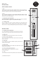
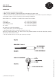
9. PAN
The pan control continuosly sends variable amounts of the post fader sig-
n
al to either the left or right main channels. In the center position, equal
amounts of signal are sent to the left and right channels.
10. PFL
You can monitor the signal of the only channel which PFL switch is turned
"ON". Usage by headphone is useful. When PFL switch turned on, other
channels are cut off automatically.
11. PEAK(PEAK LEVEL INDICATOR)
A red LED indicates a signal level at the insert return point, premaster
fader. It illuminates at approximately 5dB below clipping.
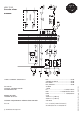
12. CHANNEL FADER
This is to adjust the volume of signal connection into each channel and
adjust the volume of output, together with the master fader. Normal opera-
tion is at the "0" mark, providing 4dB of gain above that point, if required.
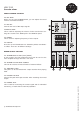
MASTER SECTION
13. STEREO GRAPHIC EQUALIZER
2 x 7-band equalizer is provided for tone control over each fre-
quency, and for precise high quality sound by final tone control.
14. POWER LED
The POWER LED will illuminate when the mix
er is turned on.
I5. OUTPUT LEVEL INDICA
TOR
This is a lev
el meter which shows output levels of left & right
channel operation.
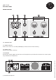
16. TAPE LEVEL
You can adjust the volume of TAPE-in signal by this when con-
necting a tape recorder.
17. EFFECT LEVEL
By using this control, you can adjust the signal level of echo
repeat & exteral effcects.
18. 0UTPUT MAIN FADER(LEFT/RIGHT)
This is a master fader for adjustment for volume
of left/right output.
19. +48V
The LED will be illuminate when phantom power starts working.
© US Blaster Europe BV