T O T A L C O N T R O L MP/8 V.34 Getting Started 1996 U.S. Robotics Access Corporation 1800 West Central Road Mount.
U.S. Robotics and the U.S. Robotics logo are registered trademarks of U.S. Robotics Access Corporation. Total Control is a trademark of U.S. Robotics Access Corporation. Any trademarks, tradenames, service marks, or service names owned or registered by any other company and used in these release notes are the property of their respective companies.
U.S. Robotics, the U.S. Robotics logo, and MP/8 V.34 are registered trademarks of U.S. Robotics Access Corporation. V.Fast Class and V.FC are trademarks of Rockwell International. Any trademarks, trade names, service marks or service names owned or registered by any other company and used in this manual are the property of their respective companies. 1996 U.S. Robotics Access Corp. 8100 N. McCormick Blvd.
Table of Contents About This Manual Chapter 1 Introduction About the MP/8 V.34 modems Status Indicators Features Modem Compatibility Chapter 2 Installing the MP/8 V. 34 modem Requirements Package Contents Installing the MP/8 V.
About This Manual This manual explains how to set up and start using your Total Control MP/8 V34. Refer to the V.Everything Command Reference manual, also included with the MP/8 V.34, for thorough explanation of the complete set of commands.
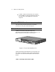
Chapter 1 Introduction The Total Control MP/8 V.34 modem integrates eight data channels, which utilize the latest modem technology into one compact unit. MP/8 V.34 is a versatile unit that fits into numerous system setups. Here are a few examples: In a Local Area Network... the MP can be interfaced to a terminal server or a router, allowing multiple users remote access to your network. As a Front End for Remote Access... the MP may front-end a rack of PCs running remote access operations.
1-2 MP/8 V.34: Getting Started In a BBS... the MP can be hooked up to a computer running a BBS via a COM port expansion module. All the calls coming in to the BBS will come through a single unit. About the MP/8 V.34 modems This section briefly describes the functions of the Status Indicators, the Telco jacks, and the RS-232 jacks. Status Indicators The MP/8 V.34 modems display their status using light -emitting diodes (LEDs) that are visible from the front. The MP/8 V.
Introduction 1-3 Appearance Off Amber blink (8 per second) Amber blink (1 per second) Green blink (1 per second) Green Amber Red Red blink (1 per second) Meaning Idle, ready to make or receive calls Looking for U interface Looking for S/T interface U and S/T interfaces found; waiting for line to become active Connection OK Negotiating (training) with a remote analog device U interface not found Incorrect SPID Telco Jacks The Telco jacks located on the back panel provide access to the phone lines through
1-4 MP/8 V.34: Getting Started Features High-Speed Connections With the V.34 Everything and the V.Fast Class modulation scheme, two modems can connect at rates up to 31.2 Kbps and 33.6 Kbps when connecting with other U.S. Robotics modems with 33.6 Kbps capability. V.32 bis modems connect at rates up to 14.4K bps. Custom Configurations You can create custom configurations to use as default settings and store them in Non-Volatile Random Access Memory (NVRAM) .
Introduction 1-5 HELP Screens The modem displays screens that summarize the command sets, Dial command options, and S-Register functions. See Chapter 3. Modem Compatibility Total Control MP modems adhere to the following modulation schemes and standards, ensuring com patibility with a wide base of installed modems. Note: The International Telecommunication Union (ITU-T) was formerly the International Telegraph and Telephone Consul tative Committee (CCITT). ITU-T V.34 28.8K/26.4K/24K/21.6K/19.2K/16.
1-6 MP/8 V.34: Getting Started ITU-T V.
Chapter 2 Installing the MP/8 V. 34 modem Requirements A computer or terminal with a serial port that uses standard EIA RS -232 signaling. A serial cable with a male DB -25 connector on one end and a connector that is appropriate for your computer’s serial port on the other. A Phillips screwdriver. If you’re rack -mounting the MP/8 V.34 modem, screws that are appropriate for your equipment rack. Computers or terminals with up to eight serial ports that use standard EIA RS -232 signaling.
2-2 MP/8 V.34: Getting Started Installing the MP/8 V.34 The Total Control MP is designed to be used either stand -alone or mounted in a standard 19 -in. equipment rack. Follow the instructions for the installation method that suits your needs. Important! ♦ Do not block the vents on the right side of the unit. ♦ Keep the unit in a dry place at room temperature. ♦ If using the unit as a stand -alone, keep it on a flat surface. This will leave room above and below for adequate ventilation.
Installing the MP/8 V.34 2-3 Figure 2-1. Attaching a Mounting Bracket. 3 Installing the unit in the rack. Most racks come with the necessary screws and nuts/anchors to install rack mounted devices. a First, gather four screws and enough nuts/anchors for the screws. b Then, holding the unit in the rack and supporting it from underneath with one hand, insert screws in the bottom left and bottom right slots and start threading them. See Figure 2-2.
2-4 MP/8 V.34: Getting Started Figure 2-2. Mounting an MP/8 V.34 modem in a rack. c Insert screws in the top left and top right slots and start threading them. d Beginning with the two bottom screws, tighten all four until the unit is secure. Setting the DIP Switches The DIP switches, located on the rear panel between the RS-232 and Telco ports, are for adapting the modem to your equipment and system requirements. Each set of DIP switches controls 8 modems. Figure 2.
Installing the MP/8 V.34 2-5 Figure 2.3—DIP Switch Factory Settings Table 2.
2-6 MP/8 V.
Installing the MP/8 V.34 2-7 45 to DB-9 adapters. Use these to plug the cable into the terminals or network. 4. Plug the power cable into the power jack at the back of the unit. Plug the cable into a standard 115-volt AC wall socket. 5. Power on the unit. The Run/Fail LED should emit a green light. If it does not indicate that the power is on, make sure the power cable is attached tightly and the power switch is on.
Chapter 3 Configuring the Modems Total Control MP modems are factory configured to run under hardware flow control. Once the unit is set up, nothing else needs to be done—the unit is all ready to operate. However, the modems can be configured for specialized systems or situations. The modems use a superset of the standard AT command set for dial-up modems. The commands control configuration options as well as modem operations such as diagnostic testing.
3-2 MP/8 V.34: Getting Started Default—Hardware Flow Control Template—&F1 When the Total Control MP is first turned on, the modems automatically load the hardware flow control template into active RAM from Non-Volatile Random Access Memory (NVRAM). The Hardware Flow Control template, though stored in ROM, is also stored in NVRAM as the current settings. Unless a modem is programmed for another template, it will operate under this configuration.
Configuring and Testing Using the Windows Utility3-3 Table 3.
3-4 MP/8 V.34: Getting Started Software Flow Control Template—&F2 This template is the same as &F1, except &F2 uses software flow control. Table 3.2 on the opposite page lists the configuration command settings of the software flow control template. Settings different from the default template are noted in bold. The modem sends the computer or terminal the standard ASCII Transmit OFF (XOFF) character, -S, when its buffer nears 90% capacity.
Configuring and Testing Using the Windows Utility3-5 Options Table 3.
3-6 MP/8 V.34: Getting Started No Flow Control Template—&F0 This template does not include features such as a fixed serial port rate or hardware flow control. Table 3.4 on the opposite page lists all the configuration settings with differences from the default template noted in bold. Recommended Uses This is good for low-performance situations. It offers compatibility with non-typical computers, older equipment, or software that cannot handle flow control and other features.
Configuring and Testing Using the Windows Utility3-7 * Detected by the modem from the AT prefix of the &W com mand that writes your defaults to NVRAM. Set your software to the desired word length, parity, and serial port rate defaults before sending the modem the AT . . . &W string. Accessing the Modems In order to perform the operations in this manual, the modems must be accessed one at a time. To access a modem: 1. Flip DIP switch 3 ON and DIP switch 4 OFF.
3-8 MP/8 V.34: Getting Started The AT command alerts the modem that other commands follow. The &F2 command tells the modem to load ROM template 2, Software Flow Control, as the active settings. This command can be used to call up the other templates as well—simply replace the 2 with a 0 for the No Flow Control template, or a 1 for the Hardware Flow Control template. The &W command stores the current settings to NVRAM. This command may also be used to store any on-the-fly changes into NVRAM.
Configuring and Testing Using the Windows Utility3-9 Using S-Registers The S-Registers are used to set various timing parameters, redefine selected ASCII characters, and other configuration options. They remain the same in all the ROM templates, but can be reconfigured for special purposes. A detailed summary of the S-Register functions is in Appendix B. Table 3.4 on the next page lists all the S-Register options that are stored in NVRAM. For a detailed description, see Appendix B.
3-10 MP/8 V.34: Getting Started Table 3.4 S-Registers Stored in NVRAM NVRAM S-Register Options S0 S1 S2 S3 S4 S5 S6 S7 S8 S9 S10 S11 S12 S13 S15 S19 S21 S22 S23 S24 S25 S26 S27 S28 S29 S33 S34 S38 S41 S42 S43 S44 S51 S53 S54 S55 S56 S57 S58 Sets number of rings for Auto Answer* Counts number of rings Escape code character Carriage Return character Line Feed character Backspace character Dial wait-time, sec. Carrier wait-time, sec. Dial pause, sec. Carrier Detect time, 1/10th sec.
Appendix A Notices Service/Support To obtain service under this warranty, contact U.S. Robotics Corporate/Systems Support as described below. Be sure to have the product’s serial number handy if you call, or send copies if you are contacting us by mail. Contacting USR Check the Cor/ Sys Customer Support card that came with your Modem pool for information about how to contact us.
A-2 MP/ 8 V.34: Getting Started Notices IC (Industry Canada) This digital apparatus does not exceed the Class A limits for radio noise emissions from digital apparatus set out in the radio interference regulations of Industry Canada (formerly Canadian Department of Communications).
Notices A-3 monitoring reception when the MP I -modem is on and off, try to correct the problem with one or more of the following measures. ♦ Reorient the receiving antenna. ♦ Relocate the computer with respect to the receiver. ♦ Relocate the computer and/or the receiver so that they are on separate branch circuits. If necessary, consult your dealer or an experienced radio/ television technician for additional suggestions.
A-4 MP/ 8 V.34: Getting Started supplier. Any repairs or alterations made by a user to this equipment, or equipment malfunctions, may give the telecommunications company cause to request the user to disconnect the equipment. For your own protection, make sure that the electrical ground connections of the power utility, telephone lines, and internal metallic water pipe system, if present, are connected together. This precaution may be particularly important in rural areas.
Index C M cabling the MP/8 V.34, 2-6 call types allowed, 1-4 connecting cables, 2-6 contents of package, 2-1 MP/8 V.