Owner’s Operation and Instruction Manual MODELS: 2000, 2500 SAFETY TESTED TO UL 1482 US ENVIRONMENTAL PROTECTION AGENCY PHASE II CERTIFIED WOODSTOVE WASHINGTON STATE APPROVED MOBILE HOME APPROVED (US ONLY) CAUTION! Read All Instructions Carefully Before Starting The Installation or Operating This Heater. Improper Installation Could Void Your Warranty! SAFETY NOTICE: If this heater is not properly installed, a house fire may result. For your safety, follow the installation instructions.
CONGRATULATIONS! You’ve purchased a heater from North America’s oldest manufacturer of wood burning products. By heating with wood you’re helping to CONSERVE ENERGY! Wood is our only Renewable Energy Resource. Please do your part to preserve our wood supply. Plant at least one tree each year. Future generations will thank you. The instructions pertaining to the installation of your wood stove comply with UL-1482 standards.
Tools and Materials Needed For Installation You will need a drill with a 1/8” bit to install sheet metal screws into connector pipe. A 5/16” socket/wrench or screw driver to install pedestal trim, room air deflector, and blower assembly described below. A 1/2” socket/wrench to install flue collar. A non-combustible floor protector as specified in this manual. All chimney and chimney connector components required for your particular chimney installation. For mobile homes, see page 13.
BLOWER ASSEMBLY INSTRUCTIONS THE BLOWER ASSEMBLY MUST BE DISCONNECTED FROM THE SOURCE OF ELECTRICAL SUPPLY BEFORE ATTEMPTING THE INSTALLATION. Step 1. Fix the assembly to the back of the stove with the four screws provided. THE BLOWER ASSEMBLY IS INTENDED FOR USE ONLY WITH A STOVE THAT IS MARKED TO INDICATE SUCH USE. DO NOT ROUTE THE SUPPLY CORD NEAR OR ACROSS HOT SURFACES! PEDESTAL TRIM ASSEMBLY Assemble trim pieces as shown with the screws provided in the parts bag. Washers may not be necessary.
INSTALLATION SAFETY NOTICE • IF THIS STOVE IS NOT PROPERLY INSTALLED, A HOUSE FIRE MAY RESULT. TO REDUCE THE RISK OF FIRE, FOLLOW THE INSTALLATION INSTRUCTIONS. FAILURE TO FOLLOW INSTRUCTIONS MAY RESULT IN PROPERTY DAMAGE, BODILY INJURY, OR EVEN DEATH. • CONSULT YOUR MUNICIPAL BUILDING DEPARTMENT OR FIRE OFFICIALS ABOUT RESTRICTIONS AND INSTALLATIONS REQUIREMENTS IN YOUR AREA. • USE SMOKE DETECTORS IN THE ROOM WHERE YOUR STOVE IS INSTALLED. • KEEP FURNITURE AND DRAPES WELL AWAY FROM THE STOVE.
FLOOR PROTECTOR Your wood stove should be placed on a 1 inch, non-combustible surface with a k factor of 0.84. For multiple layers, add R-values of each layer to determine the overall R-value. The R value for the required board is 1.2. The floor protector should be under the stove, twenty-six inches beyond the front and six inches beyond each side of the fuel loading and ash removal opening.
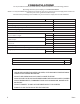
CLEARANCES TO COMBUSTIBLES It is of utmost importance that the clearances to combustible materials be strictly adhered to during installation of the stove. Refer to the tables below : Model 2000 2500 Single Wall Pipe (Double Wall Pipe) A B C D E 20(14) 22(20) 22.5(16.5) 32(30) 12(11) 12 20 16 30 10.5 F 22(21) 20 • Floor to ceiling height must be at least 7’ (84”) in all cases. • Do not place any combustible material within 48” of the front of the unit.
CHIMNEY CONNECTOR (STOVE PIPE) Your chimney connector and chimney must have the same diameter as the stove outlet (6”). If this is not the case, we recommend you contact your dealer in order to insure there will be no problem with the draft. The stove pipe must be made of aluminized or cold roll steel with a minimum thickness of 0.021” or 0.53 mm. It is strictly forbidden to use galvanized steel. Your smoke pipe should be assembled in such a way that the male section (crimped end) of the pipe faces down.
CHIMNEY Your wood stove may be hooked up with a 6” factory built or masonry chimney. If you are using a factory built chimney, it must comply with UL 103 standard; therefore it must be a Type HT (2100°F). It is extremely important that it be installed according to the manufacturer’s specifications. If you are using a masonry chimney, it is important that it be built in compliance with the specifications of the National Building Code.
FACTORY BUILT CHIMNEY : When a metal prefabricated chimney is used, the manufacturer’s installation instructions must be followed. You must also purchase (from the same manufacturer) and install the ceiling support package or wall pass-through and “T” section package, firestops (where needed), insulation shield, roof flashing, chimney cap, etc. Maintain proper clearance to the structure as recommended by the manufacturer.
MASONRY CHIMNEY : Ensure that a masonry chimney meets the minimum standards of the National Fire Protection Association (NFPA) by having it inspected by a professional. Make sure there are no cracks, loose mortar or other signs of deterioration and blockage. Have the chimney cleaned before the stove is installed and operated. When connecting the stove through a combustible wall to a masonry chimney, special methods are needed.
Combustible Wall Chimney Connector Pass-Throughs Method A. 12” (304.8 mm) Clearance to Combustible Wall Member: Using a minimum thickness 3.5” (89 mm) brick and a 5/8” (15.9 mm) minimum wall thickness clay liner, construct a wall passthrough. The clay liner must conform to ASTM C315 (Standard Specification for Clay Fire Linings) or its equivalent. Keep a minimum of 12” (304.8 mm) of brick masonry between the clay liner and wall combustibles.
OUTSIDE COMBUSTION AIR Your wood stove is approved to be installed with an outside air intake which is necessary for a mobile home. This type of installation is also required in air tight houses and houses with negative pressure problems. You can purchase this option through your heater dealer. Make sure to specify the part number mentioned in this booklet. Installation instructions are supplied with the air intake kit. Outside combustion air may be required if : 1.
WOODSTOVE UTILIZATION Your heating unit was designed to burn wood only; no other materials should be burned. Waste and other flammable materials should not be burned in your stove. Any type of wood may be used in your stove, but specific varieties have better energy yields than others. Please consult the following table in order to make the best possible choice. TYPE WEIGHT PER CORD EFFICIENCY RANKING SPLITS MILLIONS BTU’s/CORD Hickory 63 4500 1.0 Well 31.5 White Oak 48 4100 .
THE FIRST FIRES The fresh paint on your stove needs to be cured to preserve its quality. Once the fuel charge is properly ignited, only burn small fires in your stove for the first four hours of operation. Never open the air control more than necessary to achieve a medium burn rate. Make sure that there’s enough air circulation while curing the stove. The odors could be smelled during the 3 or 4 first fires. Never start your stove outside. You will not be able to see if you are over heating.
WARNINGS • NEVER OVERFIRE YOUR STOVE. IF ANY PART OF THE STOVE STARTS TO GLOW RED, OVER FIRING IS HAPPENING. READJUST THE AIR INTAKE CONTROL AT A LOWER SETTING. • THE INSTALLATION OF A LOG CRADLE or GRATES IS NOT RECOMMENDED IN YOUR WOOD STOVE. BUILD FIRE DIRECTLY ON FIREBRICK. • NEVER PUT WOOD ABOVE THE FIREBRICK LINING OF THE FIREBOX. RELOADING Once you have obtained a good bed of embers, you should reload the unit.
ASH DISPOSAL Ashes should be removed from the stove every few days or when ashes get to 2 to 3 inches deep. Always empty the stove when it is cold, such as in the morning. Always dispose of ashes in a metal container with a tight fitting lid. Place this container on a non combustible floor or on the ground, well away from all combustible materials, pending final disposal.
REPAIR PARTS 19 20 17 21 18 37 16 15 11 2 3 4 5 6 7 12 10 13 8 29 14 9 27 1 28 30 31 36 35 34 32 33 Feed Door Assembly 6 5 1 24 25 23 26 22 7 8 10 11 3 4 9 2 18 Ussc
REPAIR PARTS Key Part No. Description 1 2 3 4 5 6 7 69515MB 25080B 83508 83338 891373 83045A 83274 Feed Door Assy. Feed Door Latch 5/16-18 x 3/4 Hex Head Bolt 5/16-18 Lock Nut Door Hinge Pad Washer, 3/8” ID x 7/8” OD 3/8-16 Lock Nut 86643 Tube, Secondary Air (Ø0.16 holes) 2000 1 2500 2 Tube, Secondary Air (Ø0.22 holes) 2000 2 2500 2 8 9 10 11 86645 891515 88146 88138 Model 1 1 1 1 2 2 2 Retainer, Tube (1 per Secondary Tube) Refractory Insulation Qty.
HOW TO ORDER REPAIR PARTS THIS MANUAL WILL HELP YOU OBTAIN EFFICIENT, DEPENDABLE SERVICE FROM YOUR HEATER, AND ENABLE YOU TO ORDER REPAIR PARTS CORRECTLY. KEEP THIS MANUAL IN A SAFE PLACE FOR FUTURE REFERENCE. WHEN WRITING, ALWAYS GIVE THE FULL MODEL NUMBER WHICH IS ON THE NAMEPLATE ATTACHED TO THE HEATER. WHEN ORDERING REPAIR PARTS, ALWAYS GIVE THE FOLLOWING INFORMATION AS SHOWN IN THIS LIST: 1. THE PART NUMBER 2. THE PART DESCRIPTION 3. THE MODEL NUMBER: 2000 2500 4.