U USSC E STATES ST OV TED NI UNITED STATES STOVE COMPANY “Keeping North America Warm Since 1869” COMPANY King/Ashley Pellet Stove models 5500/5500M/5500XL 5500XL 5500M 5500 Owner’s Manual Please read this entire manual before installation and use of this appliance. Failure to follow these instructions could result in property damage, bodily injury, or even death.
Table of Contents TABLE OF CONTENTS............................................................................................... 2 Warranty registration . ...............................................................................3-4 Safety Precautions............................................................................................ 5 Specifications........................................................................................................ 6 Heating Specifications................
CUT HERE " WARRANTY INFORMATION CARD Name__________________________________________ Telephone #: (_____)_____________ City____________________________________________ State_______ Zip_________________ Email Address __________________________________________________________________ Model # of Unit________________________________ Serial #___________________________ Fuel Type: qWood qCoal qPellet qGas qOther _________________________ Place of Purchase (Retailer)___________________________________________
CUT HERE " Fold Here Fold Here É United States Stove Company P.O.
Safety Precautions IMPORTANT: Read this entire manual before installing and operating this product. Failure to do so may result in property damage, bodily injury, or even death. Proper installation of this stove is crucial for safe and efficient operation. Install vent at clearances specified by the vent manufacturer. Do not connect the pellet vent to a vent serving any other appliance or stove. Do not install a flue damper in the exhaust venting system of this unit.
Specifications Heating Specifications Fuel Burn Rate* 2.0 - 6.0 lbs./hr. (0.9 - 2.7 kg/hr) Burn Time (lowest setting) 5500/5500M - 60 hrs. 5500XL - 160 hrs. Hopper Capacity 5500/5500M - 120lbs. (55kg) 5500XL - 320lbs.(146kg) * Pellet size may effect the actual rate of fuel feed and burn times. Fuel feed rates may vary by as much as 20%. Use PFI listed fuel for best results. Dimensions 5500/5500M 5500XL Height 34 in. (864mm) 47 1/4 in. (1200mm) Width 26 in. (660mm) 26 in.
Installation Installation Options Read this entire manual before you install and use your pellet stove. Failure to follow instructions may result in property damage, bodily injury, or even death! (See specific installation details for clearances and other installation requirements) A Freestanding Unit—supported by pedestal/legs and placed on a non-combustible floor surface in compliance with clearance requirements for a freestanding stove installation.
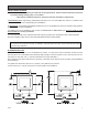
Installation Clearances Your pellet stove has been tested and listed for installation in residential, mobile home, and alcove applications in accordance with the clearances given in FIGURES 3-5 and TABLE 1. NOTE: Distance “C” on the left-hand side of your pellet stove may need to be greater than the minimum required clearance for suitable access to the control panel.
Installation Venting requirements Install vent at clearances specified by the vent manufacturer. Do not connect the pellet vent to a vent serving any other appliance or stove. Do not install a flue damper in the exhaust venting system of this unit. The following installation guidelines must be followed to ensure conformity with both the safety listing of this stove and to local building codes. Do not use makeshift methods or compromise in the installation.
Installation Vent termination clearances: A) Minimum 4-foot (1.22m) clearance below or beside any door or window that opens. B) Minimum 1-foot (0.3m) clearance above any door or window that opens. C) Minimum 3-foot (0.91m) clearance from any adjacent building. D) Minimum 7-foot (2.13m) clearance from any grade when adjacent to public walkways. E) Minimum 2-foot (0.61m) clearance above any grass, plants, or other combustible materials. F) Minimum 3-foot (0.
Installation THROUGH THE WALL INSTALLATION (Recommended installation) Canadian installations must conform to CAN/CSA-B365. To vent the unit through the wall, connect the pipe adapter to the exhaust motor adapter. If the exhaust adapter is at least 18 in.(457mm) above ground level, a straight section of pellet vent pipe can be used through the wall.
Installation Outside Air Supply (optional, unless installing in a mobile home) Depending on your location and home construction, outside air may be necessary for optimal performance. Metal pipe (solid or flexible) must be used for the outside air installation. PVC pipe is NOT approved and should NEVER be used.
Understanding your stove How your stove works Your pellet stove utilizes a inclined auger fuel feed system that is operated by a microprocessor controlled digital circuit board. The digital circuit board allows the inclined auger fuel feed system to run in a timer-based, non-continuous cycle; this cycling allows the auger to run for a predetermined period of seconds. The auger pushes pellets up a chute located at the front/bottom of the hopper which in turn falls through another chute into the burnpot.
Control Panel Overview Turning the heater ON/OFF, as well as adjustments for the fuel feed rate and room fan speed are performed by pressing the appropriate button(s) on the control panel which is located on the lower left-hand side of your heater. This unit can be changed between an automatic operation or a manual operation. The controller comes default in the automatic mode. • ON/OFF Pressing the “ON” button on the control panel will begin the start-up sequence for the heater.
Operation UNIT PREPARATION After carefully unpacking and reading the instructions for installing your stove, you will need to perform the following steps: • Attach the included spring handle to the door handle by screwing it on in a respective location. • Attach the electrical cord to the back of the stove first; then plug it into a 110-volt outlet (an outlet surge protector is highly recommended).
Operation START-UP PROCEDURE DO NOT USE CHEMICALS OR FLUIDS TO START THE FIRE - Never use gasoline, gasoline-type lantern fuel, kerosene, charcoal lighter fluid, or similar liquids to start or “freshen up” a fire in this stove. Keep all such liquids well away from the stove while it is in use. DO NOT BURN GARBAGE OR FLAMMABLE FLUIDS SUCH AS GASOLINE, NAPHTHA, OR ENGINE OIL. HOT WHILE IN OPERATION. KEEP CHILDREN, CLOTHING AND FURNITURE AWAY. CONTACT MAY CAUSE SKINS BURNS. 1.
Operation DAILY OPERATION The hopper and stove top will be hot during operation; therefore, you should always use some type of hand protection when refueling your stove. Never place your hand near the auger while the stove is in operation. This unit should be filled when the hopper level drops below 3-inches. In the event of a power outage, the stove will not function.
Maintenance Interior Chambers Periodically remove and clean the burnpot and the area inside the burnpot housing. In particular it is advisable to clean out the holes in the burnpot to remove any build up that may prevent air from moving through the burn pot freely. Remove the two(2) plates on each side of the burnpot housing and clean out that rear chamber. If a vacuum is used to clean your stove, we suggest using a vacuum designed for ash removal. Some regular vacuum cleaner (i.e.
Trouble Shooting Disconnect the power cord before performing any maintenance! NOTE: Turning the ON/OFF Switch to ”OFF” does not disconnect all power to the electrical components of the stove. Never try to repair or replace any part of the stove unless instructions for doing so are given in this manual. All other work should be done by a trained technician.
Error Codes and Display Indicators Error Code Error Descrption Possible Causes Err1 The high limit temperature sensor has tripped. • • • • Inadequate ventilation. Room fan failure. Exhaust Blockage. Electrical Open in wiring. Err2 Stove ran out of fuel during normal operation. • • • • Hopper Empty. Auger output failure or jam. Flame of fuel quality caused fire to burn too slowly or go out. Electrical Open in wiring.
Parts Diagram/List models 5500, 5500M & 5500XL Model 5500 7 3 8 4 6 12 1 9 12 9 10 9 10 10 11 5 13 2 PARTS LIST Item Part No. Title Qty. Item Part No. Title Qty. 1 2 3 4 5 6 7 25490 891166 891188 891186 25517 891168 88082 Door Weldment Ceramic Glass Glass Retainer, Top Glass Retainer, Bottom Handle, Door Latch, Door 3/4” Rope Gasket 1 1 1 1 1 1 4.
Parts Diagram model 5500, 5500M and 5500XL Note: All repair parts (other than Cabinet Sides, Hopper Assy., and Door Assy.) are same for models 5500, 5500M and 5500XL.
Parts List model 5500/5500M/5500XL PARTS LIST Item Part No. Title Qty. Item Part No. Title Qty. 1 2 3 4 5 6 7 8 9 10 10.1 10.2 10.3 11 11.1 11.2 11.
Wiring Diagram BLACK GRAY How to Order Repair Parts This manual will help you obtain efficient, dependable service from your heater, and enable you to order repair parts correctly. Keep this manual in a safe place for future reference. When writing, always give the full model number which is on the nameplate attached to the heater. When ordering repair parts, always give the following information as shown in this list: 3. The model number:____________________ 4.