UNITED STATES STOVE COMPANY “Keeping North America Warm Since 1869” King/Ashley Pellet Stove Models 5500/5500M/5500XL 5500XL 5500M 5500 Please read this entire manual before installation and use of this appliance. Failure to follow these instructions could result in property damage, bodily injury, or even death. Contact your local building or fire officials about obtaining permits, restrictions and installation inspection requirements in your area. Save these instructions.
Safety Precautions This manual describes the installation and operation of the King/Ashley, 5500, 5500XL, 5500M wood heater. This heater meets the 2015 U.S. Environmental Protection Agency's crib wood emission limits for wood heaters sold after May 15, 2015. Under specific test conditions this heater has been shown to deliver heat at rates ranging from 9,126 to 27,677 Btu/hr. IMPORTANT: Read this entire manual before installing and operating this product.
Specifications HEATING SPECIFICATIONS Fuel Burn Rate* 2.0 - 6.0 lbs./hr. (0.9 - 2.7 kg/hr) Burn Time (lowest setting) 5500/5500M - 60 hrs. 5500XL - 160 hrs. Hopper Capacity 5500/5500M - 120lbs. (55kg) 5500XL - 320lbs.(146kg) * Pellet size may effect the actual rate of fuel feed and burn times. Fuel feed rates may vary by as much as 20%. Use PFI listed fuel for best results. DIMENSIONS 5500/5500M 5500XL Height 34 in. (864mm) 47 1/4 in. (1200mm) Width 26 in. (660mm) 26 in.
Installation This heater is designed to burn only PFI Premium grade pellets. This appliance can also burn pellets rated as standard after May 16, 2015 DO NOT BURN: 1. Garbage; 8. Railroad ties or pressure-treated wood; 2. Lawn clippings or yard waste; 9. Manure or animal remains; 3. Materials containing rubber, including tires; 10. Salt water driftwood or other previously salt water saturated materials; 4. Materials containing plastic; 5.
FLOOR PROTECTION This unit must be installed on a non-combustible floor surface. If a floor pad is used, it should be UL listed or equal. The floor pad or non-combustible surface should be large enough to extend a minimum of 6 in. (152.4mm) in front, 6 in. (152.4mm) on each side, and 1 in. (25.4mm) behind the stove (see FIGURE 1). Floor protection must extend under and 2 in. (50.8mm) to each side of the chimney tee for an interior vertical installation (see FIGURE 2).
CLEARANCES Your pellet stove has been tested and listed for installation in residential, mobile home, and alcove applications in accordance with the clearances given in FIGURES 3-5 and TABLE 1. Clearances may only be reduced by means approved by the regulatory authority. NOTE: Distance “C” on the left-hand side of your pellet stove may need to be greater than the minimum required clearance for suitable access to the control panel.
VENTING REQUIREMENTS Install vent at clearances specified by the vent manufacturer. Do not connect the pellet vent to a vent serving any other appliance or stove. Do not install a flue damper in the exhaust venting system of this unit. The following installation guidelines must be followed to ensure conformity with both the safety listing of this stove and to local building codes. Do not use makeshift methods or compromise in the installation.
PELLET VENT TERMINATION Do not terminate the vent in an enclosed or semi-enclosed area, such as; carport, garage, attic, crawl space, under a sundeck or porch, narrow walkway, or any other location that can build up a concentration of fumes. The termination must exhaust above the outside air inlet elevation. The termination must not be located where it will become plugged by snow or other materials. Do not terminate the venting into an existing steel or masonry chimney.
THROUGH THE WALL INSTALLATION (RECOMMENDED INSTALLATION) Canadian installations must conform to CAN/CSA-B365. To vent the unit through the wall, connect the pipe adapter to the exhaust motor adapter. If the exhaust adapter is at least 18 in.(457mm) above ground level, a straight section of pellet vent pipe can be used through the wall.
OUTSIDE AIR SUPPLY (optional, unless installing in a mobile home) Depending on your location and home construction, outside air may be necessary for optimal performance. Metal pipe (solid or flexible) must be used for the outside air installation. PVC pipe is NOT approved and should NEVER be used. A wind shield over the termination of the outside air pipe or a 90-degree elbow or bend away from the prevailing winds MUST be used when an outside air pipe is installed through the side of a building.
ber by the exhaust or draft fan must be maintain precisely. Too little air will result in a flame that is non-energetic y. If the fuel continues to flow with too little air for long enough, the burn pot will fill with too much fuel and the fire mother out. To much air will result in a flame that is overactive or aggressive. The flame in this situation is typically blue at the bottom and resembles a blow torch.
Control Panel Overview Turning the heater ON/OFF, as well as adjustments for the fuel feed rate and room fan speed are performed by pressing the appropriate button(s) on the control panel which is located on the lower left-hand side of your heater. This unit can be changed between an automatic operation or a manual operation. The controller comes default in the automatic mode. • ON/OFF Pressing the “ON” button on the control panel will begin the start-up sequence for the heater.
Thermostat Hook-Up Must Remove Jumper First 1. Put female plug fittings on the lead wires to your low voltage thermostat. 2. Plug one thermostat lead onto each of the terminal posts on the circuit board. 3. The stove will now drop back to heat setting 1.
Operation UNIT PREPARATION After carefully unpacking and reading the instructions for installing your stove, you will need to perform the following steps: • Attach the included spring handle to the door handle by screwing it on in a respective location. • Attach the electrical cord to the back of the stove first; then plug it into a 110-volt outlet (an outlet surge protector is highly recommended).
START-UP PROCEDURE DO NOT USE CHEMICALS OR FLUIDS TO START THE FIRE - Never use gasoline, gasoline-type lantern fuel, kerosene, charcoal lighter fluid, or similar liquids to start or “freshen up” a fire in this stove. Keep all such liquids well away from the stove while it is in use. DO NOT BURN GARBAGE OR FLAMMABLE FLUIDS SUCH AS GASOLINE, NAPHTHA, OR ENGINE OIL. HOT WHILE IN OPERATION. KEEP CHILDREN, CLOTHING AND FURNITURE AWAY. CONTACT MAY CAUSE SKINS BURNS. DO NOT USE GRATES OR ELEVATE THE FIRE.
DAILY OPERATION The hopper and stove top will be hot during operation; therefore, you should always use some type of hand protection when refueling your stove. Never place your hand near the auger while the stove is in operation. This unit should be filled when the hopper level drops below 3-inches. In the event of a power outage, the stove WILL NOT function.
Maintenance Failure to clean and maintain this unit as indicated can result in poor performance and safety hazards. Unplug your stove’s electrical cord prior to removing the back panel or opening the exhaust system for any inspection, cleaning, or maintenance work. Never perform any inspections, cleaning, or maintenance on a hot stove. Do not operate stove with broken glass , leakage of flue gas may result. WARNING THE CHIMNEY AND CHIMNEY CONNECTOR MUST BE KEPT IN GOOD CONDITION AND CLEAN.
BLOWER MOTORS Clean the air holes on the motors of both the exhaust and distribution blowers annually. Remove the exhaust blower from the exhaust duct and clean out the internal fan blades as part of your fall start-up. PAINTED SURFACES Painted surfaces may be wiped down with a damp cloth. If scratches appear, or you wish to renew your paint, contact your authorized dealer to obtain a can of suitable high-temperature paint.
Trouble Shooting Disconnect the power cord before performing any maintenance! NOTE: Turning the ON/OFF Switch to ”OFF” does not disconnect all power to the electrical components of the stove. Never try to repair or replace any part of the stove unless instructions for doing so are given in this manual. All other work should be done by a trained technician. PROBLEM CAUSE: To rich air/fuel mixture Orange, lazy flame_excessive fuel build-up in the burnpot. • Clean out the burnpot and burnpot housing.
Error Codes and Display Indicators Error Code Error Description Possible Causes Err1 The high limit temperature sensor has tripped. • • • • Inadequate ventilation. Room fan failure. Exhaust Blockage. Electrical Open in wiring. Err2 Stove ran out of fuel during normal operation. • • • • Hopper Empty. Auger output failure or jam. Flame of fuel quality caused fire to burn too slowly or go out. Electrical Open in wiring.
Parts Diagram/List models 5500, 5500M & 5500XL Model 5500 7 3 8 4 6 12 1 9 12 9 10 9 10 10 11 5 Item Part No. Title 13 2 Qty. 1 25490 Door Weldment 1 2 891166 Ceramic Glass 1 3 891188 Glass Retainer, Top 1 4 891186 Glass Retainer, Bottom 1 5 25517 Handle, Door 1 6 891168 Latch, Door 1 7 88082 3/4” Rope Gasket 4.3 ft 8 88087 Glass Gasket 3.
Parts Diagram model 5500, 5500M and 5500XL Note: All repair parts (other than Cabinet Sides, Hopper Assy., and Door Assy.) are same for models 5500, 5500M and 5500XL.
Parts List model 5500/5500M/5500XL Item Part No. Title Qty. Item Part No. Title Qty.
CORRECT WRONG Insure the wires are connected to the bottom two prongs of the hopper switch as shown.
Service Record Service Record It is recommended that your heating system is serviced regularly and that the appropriate Service Interval Record is completed. SERVICE PROVIDER Before completing the appropriate Service Record below, please ensure you have carried out the service as described in the manufacturer’s instructions. Always use the manufacturer's specified spare part when replacement is necessary.
How to Order Repair Parts / Comment Commander Des Pièces Détachées THIS MANUAL WILL HELP YOU OBTAIN EFFICIENT, DEPENDABLE SERVICE FROM YOUR HEATER, AND ENABLE YOU TO ORDER REPAIR PARTS CORRECTLY. KEEP THIS MANUAL IN A SAFE PLACE FOR FUTURE REFERENCE. WHEN WRITING, ALWAYS GIVE THE FULL MODEL NUMBER WHICH IS ON THE NAMEPLATE ATTACHED TO THE HEATER.
Enregistrement De Service Il est recommandé que votre système de chauffage est desservi régulièrement et que le Service Interval enregistrement approprié est terminée. FOURNISSEUR DE SERVICES Avant de terminer l’enregistrement de service approprié ci-dessous, s’il vous plaît vous assurer que vous avez effectué le service tel que décrit dans le les instructions du fabricant. Toujours utiliser pièce de rechange indiquée par le fabricant lors de remplacement est nécessaire.
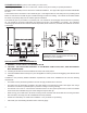
MOTEUR D'ENTRAÎNEMENT DE LA VIS SANS FIN MICRORUPTEUR ALLUMEUR SOURCE ÉLECTRIQUE BLANC BLANC MARRON MARRON BLANC ROUGE BLEU ORANGE PCB PRINCIPAL NOIR GRIS THERMISTOR BLANC BLANC SOUFFLANTE DE DISTRIBUTION NOIR NOIR VENTILATEUR D'ÉVACUATION Assurez-vous que les fils sont connectés aux deux broches inférieures de l’interrupteur de la trémie, comme illustré.
Pièce No. de pièce 86633 4 86628 3 86625 2 86624 1 69512 7 25506 6 80481 5 891164 9 69522 - 69518 8 83534 10.3 891132 10.2 891190 10.1 69513 10 83543 13 891161 12 83534 11.3 891132 11.2 891189 11.1 69514 11 891195 16 83299 15 83356 14 88117 21 80480 20 80778 19 25515 - 25511 18 25498 17 Nomenclature des modèles 5500/5500M/5500XL NOMENCLATURE Intitulé Pot de combustion Corps du pot de combustion Conduit d'évacuation (Ens.
Schéma des pièces Remarque : Toutes les pièces détachées (autres que les parois latérales de l’armoire, l’ens. de trémie et l’ens. de porte) sont identiques pour les modèles 5500, 5500M et 5500XL.
Modèle 5500 Schéma/liste des pièces 7 8 3 4 6 12 1 9 12 9 10 9 10 10 11 5 13 2 Pièce No. de pièce 88082 7 891168 6 25517 5 891186 4 891188 3 891166 2 25490 1 NOMENCLATURE Qté Pièce No.
Code d'erreur Description de l'erreur Codes d’erreur et indicateurs d’affichage Causes possibles • Moteur du ventilateur de la pièce bloqué ou défectueux. Le fusible de sortie du ventilateur de la pièce a sauté. Err8 • Moteur du ventilateur de tirage bloqué ou défectueux. Le fusible de sortie du ventilateur de tirage (ventilateur d'évacuation) a sauté. Err7 • Igniteur court-circuité ou défectueux. Le fusible de sortie de l'igniteur a sauté. Err6 • Moteur de la vis sans fin bloqué ou défectueux.
Dépannage Ne tentez jamais de réparer ou de remplacer une pièce du poêle à moins que des instructions pour le faire ne soient fournies dans ce manuel. Tous les autres travaux devront être effectués par un technicien qualifié. Déconnectez le cordon d'alimentation avant d'effectuer tout travail d'entretien ! REMARQUE : Mettre l'interrupteur ON/OFF (marche/arrêt) sur "OFF" ne coupe pas l'alimentation des composants électriques du poêle.
CHAMBRES INTÉRIEURES Retirez et nettoyez périodiquement le pot de combustion et la surface à l'intérieur du logement du pot de combustion. Il est particulièrement conseillé de nettoyer les orifices du pot de combustion afin d'éliminer toute accumulation qui pourrait empêcher l'air de circuler librement à travers le pot de combustion. Retirez les deux (2) plaques de chaque côté du logement du pot de combustion et nettoyez cette chambre arrière.
FONCTIONNEMENT QUOTIDIEN Ne placez jamais votre main près de la vis sans fin lorsque le poêle fonctionne. La trémie et le dessus du poêle seront chauds pendant l'utilisation ; par conséquent, vous devrez toujours utiliser une certaine protection au niveau des mains lorsque vous rechargerez le poêle en combustible Cette unité devra être remplie lorsque le niveau de la trémie passe en dessous de 3 pouces (7,6 cm). En cas de coupure de courant, le poêle NE FONCTIONNERA PAS.
PROCÉDURE DE MISE EN MARCHE TENTEZ D’ATTEINDRE UN TAUX DE PUISSANCE CALORIFIQUE DÉPASSANT LES SPÉCIFICATIONS DE CONCEPTION DU CHAUFFAGE PEUT LUI CAUSER DES DOMMAGES PERMANENTS. NE SURCHAUFFEZ - SI LE RADIATEUR OU DE LA CHEMINÉE GLOWS DES CONNECTEURS, IL YA EMBALLEMENT. NE PAS UTILISER DES GRILLES OU SURÉLEVER LE FEU. FAITES LE FEU DIRECTEMENT DANS LE FOYER. CHAUD DURANT LE FONCTIONNEMENT. MAINTENEZ LES ENFANTS, LES VÊTEMENTS ET LE MOBILIER ÉLOIGNÉS. TOUT CONTACT PEUT ENTRAÎNER DES BRÛLURES.
Fonctionnement PRÉPARATION DE L’UNITÉ Après avoir déballé avec précaution et lu les instructions d’installation de votre poêle, vous devrez suivre les étapes suivantes : Raccordez d’abord le cordon électrique au dos du poêle ; puis branchez-le dans une prise de 110 volts (un parasurtenseur de prise de courant est fortement recommandé). • Fixez la poignée ressort fournie à la poignée de la porte en la vissant à l’emplacement correspondant.
Vue d’ensemble du panneau de contrôle La mise en marche et l’arrêt du système de chauffage, ainsi que les réglages du taux d’approvisionnement en combustible et de la vitesse du ventilateur de la pièce sont réalisés en appuyant sur le(s) bouton(s) approprié(s) du panneau de contrôle qui se trouve(nt) sur le côté inférieur gauche de votre système de chauffage. Cette unité peut basculer entre un fonctionnement automatique ou un fonctionnement manuel. Le régulateur fonctionne par défaut en mode automatique.
amount of heat produced by the stove is proportional to the rate of the fuel that is burned, and this rate is controlled e “HEAT RANGE” setting. In order to maintain combustion of the fuel at a desired rate, the air provided to the burn ber by the exhaust or draft fan must be maintain precisely. Too little air will result in a flame that is non-energetic y. If the fuel continues to flow with too little air for long enough, the burn pot will fill with too much fuel and the fire mother out.
APPROVISIONNEMENT EN AIR EXTÉRIEUR(en option) En fonction de la construction de votre domicile et de son emplacement, de l'air venant de l'extérieur peut être nécessaire afin d'obtenir des performances optimales. Un tuyau métallique (solide ou flexible) doit être utilisé pour les installations extérieures de prise d'air. Un tuyau en PVC N'est PAS approuvé et ne devra JAMAIS être utilisé.
Raccordement Du Thermostat Doit supprimer Jumper First 1. Placez les raccords mâles sur les fils de connexion à votre thermostat basse tension. 2. Branchez un fil de thermostat sur chacun des bornes de la carte de circuit imprimé. 3. Le poêle va maintenant revenir au réglage de chaleur 1.
DÉGAGEMENTS DE L'ÉVACUATION DE TIRAGE A. B. C. D. E. F. G. H. I. Dégagement minimum de 4 pieds (1.22m) sous et à côté d'une porte ou d'une fenêtre qui s'ouvre. Dégagement minimum d'1 pied (0.3m) au-dessus d'une porte ou d'une fenêtre qui s'ouvre. Dégagement minimum de 3 pieds (0.91m) à partir de toute construction adjacente. G Dégagement minimum de 7 pieds (2.13m) de tout passage lorsqu'il est adjacent à des allées publiques. Dégagement minimum de 2 pieds (0.
EXIGENCES DE VENTILATION N'installez pas un registre de carneau dans le système de ventilation d'évacuation de cette unité. Ne raccordez pas la ventilation des granulés à une ventilation utilisée par un autre appareil ou poêle. Installez la ventilation avec les dégagements indiqués par le fabricant du système de ventilation. Les instructions d'installation suivantes doivent être respectées pour assurer la conformité avec la liste de sécurité de ce poêle et les codes locaux de construction.
DÉGAGEMENTS Votre poêle à granulés a été testé et listé pour une installation dans des applications résidentielles, des maisons mobiles et des alcôves conformément aux dégagements donnés sur les FIGURES 3 à 5 et dans le TABLEAU 1. REMARQUE : La distance "C" sur le côté gauche de votre poêle à granulés peut nécessiter un dégagement obligatoire minimum plus grand afin d'obtenir un accès commode au panneau de contrôle.
Installation COMBUSTIBLE Le chauffage est conçu pour ne brûler que des granulés de classe supérieure PFI. Cet appareil peut aussi brûler des granulés de classe ordinaire après le 16 mai 2015. NE PAS BRÛLER : 1. Des ordures; 7. Débris de construction ou de démolition; 2. Des déchets de tonte ou résidus de jardin; 8. Traverses de voie ferrée ou bois traité sous pression; 3. Des matériaux contenant du caoutchouc, incluant les pneus; 9. Fumier ou restes d’animaux; 4. Matériaux contenant du plastique; 10.
Specifications Spécifications de chauffage 5500XL - 320lbs.(146kg) 5500/5500M - 120lbs. (55kg) Capacité de la trémie 5500XL - 160 hrs. 5500/5500M - 60 hrs. Temps de combustion (réglage le plus bas) 2.0 - 6.0 lbs./hr. (0.9 - 2.7 kg/hr) Vitesse de combustion du combustible* * La taille des granulés peut affecter le taux réel d’approvisionnement en combustible et les durées de combustion. Les taux d’approvisionnement en combustible peuvent varier jusqu’à 20%.
Précautions relatives à la sécurité Ce manuel décrit l’installation et le fonctionnement du chauffage au bois, King/Ashley, 5500, 5500XL. Ce chauffage respecte les limites d’émission 2015 de bois en caisson de la U.S. Environmental Protection Agency pour les chauffages au bois solide après le 15 mai 2015. Sous les conditions spécifiques du test, ce chauffage a démontré un taux de chauffage de 9,126 à 27,677 Btu/h.
UNITED STATES STOVE COMPANY “Keeping North America Warm Since 1869” Poêle à granulés King/Ashley modèles 5500/5500M/5500XL 5500XL 5500M 5500 Agence américaine de protection de l’environnement Certifié pour se conformer aux normes d’émissions de particules de 2015. Guide d’utilisation Contactez les fonctionnaires locaux de construction ou de lutte contre les incendies pour savoir comment obtenir les permis et connaître les limitations et exigences d’inspection de l’installation de votre région.