website: www.usstove.com COAL BURNING CIRCULATOR HEATER MODELS CAC/BCAC Installation, Operation and Maintenance Instructions SAFETY NOTICE: If this heater is not properly installed, a house fire may result. For your safety, follow the installation directions. Contact local building or fire officials about restrictions and inspection requirements in your area. CAUTION: Read all instructions carefully before starting the installation or operation of this heater.
TABLE OF CONTENTS IMPORTANT SAFETY INFORMATION ............................................................................................................................................................. 2 BUILDING CODES AND SAFETY STANDARDS ............................................................................................................................................... 3 HOW THIS HEATER OPERATES ..................................................................................................
BUILDING CODES AND SAFETY STANDARDS These instructions comply with the applicable National Fire Protection Association and Underwriters’ Laboratories, Inc. Standards for the installation and operation of this type heater. Before beginning the installation, you should check with local building officials to assure compliance with local regulations and codes. This heater is safety listed by Omni Test Laboratories as specified by the listing label attached to the heater.
FIGURE 3 - MINIMUM CLEARANCES TO COMBUSTIBLES FIGURE 4 - MINIMUM CLEARANCES TO COMBUSTIBLES SIDE SECTION VIEW PLAN SECTION VIEW 4 CAC
FIGURE 5 - FLOOR PROTECTION FLOOR PROTECTION This heater has been designed to prevent excessive temperatures on the floor beneath the heater. It is important, however, that a combustible floor be protected by a 3/8 inch minimum thick noncombustible inorganic millboard having a thermal conductivity of k=0.43 BTU/ft.2/in./hr./°F or a listed floor protector beneath the heater extending beyond the heater as shown by figure 5.
There are five allowable ways that a chimney connector can be connected to a masonry chimney by passing through a combustible wall. NFPA Standard 211 allows the following wall pass-through systems. 1. Use a minimum 3-1/2" thick brick masonry wall framed into the combustible wall. A fireclay liner (ASTM C315 or equivlent) having a 5/8" minimum wall thickness must be used and it must be at least 12" away from any material that could catch fire.
There are basically two methods of metal prefabricated chimney installation. One method is to install the chimney inside the residence through the ceiling and the roof. The other method is to install an exterior chimney that runs up the outside of the residence. Single wall pipe is not legal for outside installation. REMEMBER: Follow the chimney manufacturer's installation instructions and maintain the manufacturer's specified clearance distance.
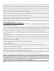
PART C FIGURE 5 MINIMUM CHIMNEY CLEARANCES FROM MASONRY TO SHEET STEEL SUPPORTS AND COMBUSTIBLES 2 IN. 24 GAUGE VENTILATED THIMBLE WITH TWO 1 INCH AIR CHANNELS CHIMNEY FLUE CHIMNEY THIMBLE TWO VENTILATED AIR CHANNELS EACH 1 INCH. CONSTRUCTED OF SHEET STEEL. MASONRY CHIMNEY CONSTRUCTED TO NFPA 211 PART D FIGURE 5 CHIMNEY CONNECTOR TO HEATER MINIMUM 6 IN. GLASS FIBER INSULATION ALL AROUND SHEET STEEL SUPPORTS (24 GAUGE MIN.
FIGURE 8 - CONNECTING HEATER’S CHIMNEY CONNECTOR TO MASONRY CHIMNEY WHEN CHIMNEY CONNECTOR DOES NOT HAVE TO PASS THROUGH A COMBUSTIBLE WALL HEATER INSPECTION Before installing the heater, inspect the heater for external damage and missing parts. Check the gaskets around the doors to assure that they are still in place. Also check inside the heater. Report any deficiencies found to your heater dealer and make sure all problems are resolved before installing the heater.
Two common types of clearance reductions systems use sheet metal with a thickness of 28 gauge (galvanized steel, aluminum, copper) or a 3-1/2 inch (4 inch thick nominal) thick masonry wall. Either of these materials must be spaced out 1 inch from the combustible surfaces. With sheet metal, noncombustible spacers are used to maintain the 1 inch air space. With a masonry wall, metal wall ties and furring strips, if needed, are used to anchor the brick to the wall.
HEATER OPERATION IMPORTANT: DO NOT USE THE HEATER UNTIL A PROFESSIONAL INSPECTION HAS BEEN MADE OF THE ENTIRE INSTALLATION BY YOUR LOCAL FIRE DEPARTMENT, FIRE MARSHAL OR BUILDING CODE INSPECTOR. INSTALL A SMOKE DETECTOR ON EACH FLOOR OF YOUR HOME; IN CASE OF ACCIDENTAL FIRE FROM ANY CAUSE IT CAN PROVIDE TIME FOR ESCAPE. This heater must be operated as outlined in this manual or a serious fire may occur.
5. When the wood is burning briskly, add additional kindling as required to establish a good kindling fire. 6. When the kindling fire has been established and is burning briskly, cover it with a thin layer of coal. If you add too much coal you will smother the fire, requiring you to start the whole process over again. Be patient. 7. Securely close the heater’s fuel feed door as the coal begins burning. See figure 10.
MINIMUM FIRE ADJUSTMENT Soot is more likely to accumulate in the chimney connector and chimney liner during extended periods of low firing. This accumulation can be reduced by proper setting of the air shutter on the ash door, see figure 9. Rotating the air shutter to allow more air into the fire chamber will increase the rate of the minimum fire and reduce the accumulation. Exoerience in a particular heating situation will give guidance in choosing the best setting.
VENTING SYSTEM (CHIMNEY CONNECTOR AND CHIMNEY) The venting system consists of the heater’s chimney connector (the pipe which connects the heater to the chimney) and the chimney itself. When coal is burned, the products of combustion combine with moisture to form a soot residue which accumulates on the flue lining. When ignited this soot makes an extremely hot fire. The chimney connector and chimney should be inspected twice a month during heating season to determine if a soot biuldup has occured.
WHAT TO DO IF THE HEATER SMOKES OR BURNS POORLY OR EXCESSIVE CREOSOTE ACCUMULATES IN THE CHIMNEY 1. Open a window slightly to see if the conditions improve. If opening a window improved the performance of the heater or stops the spillage of smoke into the room, the problem is caused by a slight vacuum in the room. The vacuum can be the result of the room being so tightly constructed that the air removed from the room by the heater is not replaced by normal infiltration of air from outside the room. 2.
QUICK REFERENCE TO THE MOST COMMON SOLUTIONS FOR THE MOST COMMON HEATER OPERATIONAL PROBLEMS Symptom: Fire rate does not increase with thermostat open, smoke spilling from feed door when tending fire or backpuffing. Check for: a. Chimney connector pushed too far into a masonry chimney thimble restricting draft. b. Chimney or chimney connector restricted with creosote. c. Chimney draft reduced by air entering through: - Unsealed chimney clean-out access. - Loose mortar or cracked chimney wall.
25. Do assemble the chimney connector so that moisture that accumulates within the chimney will flow back toward the heater. 26. Do remove the ashes from the heater regularly. 27. Do set the thermostat on “HI” and allow the heater to burn for approximately 15 minutes after fresh coal is added before reducing the thermostat setting. 28. Do store coal in such a manner that wet and dry coal will not mix. 29. Do protect your hands with noncombustible gloves when loading the heater, removing ashes, etc. 30.
FIGURE 12 ILLUSTRATION OF REPAIR PARTS. SEE LEDGER ON NEXT PAGE FOR PART NAMES AND PART NUMBERS.
SEE FIGURE 12 FOR ILLUSTRATION OF PARTS NOTICE: Parts marked with a KEY 1 2 3-4 7 8 9 11 12 13 14 15 16 17 18 19 20 21 22 23 24 25 26 27 28 29 30 31 32 33 34 PART NO.
U USSC E STATES STO D E T V NI COMPANY Keeping America Warm Since 1869 CAC/BCAC Owner's Manual When writing, always give the full model number which is on the nameplate attached to the fireplace. When ordering repair parts or options, always give the following information as shown in this list: 1. 2. 3. 4. The PART NUMBER The PART DESCRIPTION The MODEL NUMBER: CAC BCAC The SERIAL NUMBER _____________________ Save this manual for future reference.