Pixels ™ Wall Mounted Design and Installation Guide December 2012
On the cover: Pixels mural shown with GE Tetra® Power Grid during installation. For more information go to gelightingsolutions.
Design and Installation Guide Pixels™ wall-mounted Celebration™ panels from USG offer a turnkey system for displaying the unique perforated imagery art that Pixels makes possible.
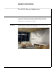
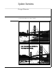
System Overview Pixels Wall-Mounted Applications Features Celebration™ panels and Celebration panels with Pixels™ imagery can be mounted to the vertical surface in two ways: directly to the surface using wall mount backer board system, or away from the vertical surface leaving a “cavity” in which to mount light sources for back lighting the image. Here are examples of each application.
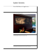
System Overview Pixels Wall-Mounted Applications Frame Mounted The backlit system is also simplified in that it uses standard Fineline® suspension – only mounted to the wall thus being quite familiar to contractors. [photo image} On the pages that follow, further explanation of the systems will clarify, in detail, how each can be used effectively depending on the design criteria and desired result.
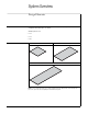
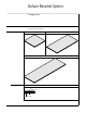
System Overview Design Elements Shape The overall shape of a wall-mounted system is determined by the size of the panels and their configuration and relationship to one another. Available panel sizes are – 28 x 28 – 28 x 48 – 28 x 68 Panels 28 x 28 Pixels Celebration Panel 28 x 48 Pixels Celebration Panel 28 x 68 Pixels Celebration Panel Note: The Pixels image and design process itself is detailed in the Pixels Design Guide, IC566.
System Overview Design Elements The Pixels panels can be arranged in any number of creative ways. As long as the 28 module dimension is honored, almost any configuration can be achieved including altering the shape of the frame itself.
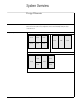
System Overview Design Elements Sample Configurations 68 x 68 Systems 2' x 2' 2' x 4' 2' x 6' 2' x 2' 2' x 2' 2' x 2' 2' x 2' 2' x 2' 2' x 2' 2' x 2' 2' x 2' 2' x 4' 2' x 4' 2' x 2' 2' x 2' 2' x 2' There is no limitation to the finished size of the system. The above examples are only to show the flexibility of panel layout and frame configuration.
System Overview Design Elements Photos can be used as is or combined with copy or graphics. Also see Pixels Design Guide (IC566) for a further understanding of Pixels graphics capabilities.
Surface-Mounted System Components In addition to the Pixels Celebration panels (see page 4), the following components are unique to the surface-mounted system.
Surface-Mounted System Components Edge Trim Backer Board Aluminum Trim Fastener Wall-Dog ™Fastener Note: Wall-Dog is a trademark of Powers Fasteners, Inc. For more information please visit www.powers.
Surface-Mounted System Construction The surface-mounted system consists of backer panels that are installed edge-to-edge directly to the wall surface.
Surface-Mounted System Construction Construction Details A. Panel Intersection adhesive backed poly bumper drywall screw B. Perimeter Edge PIXELS panel or CELEBRATIONS panel backer board backer board drywall screw PIXELS panel or CELEBRATIONS panel aluminum trim SHEETROCK gypsum panel SHEETROCK gypsum panel C.
Surface-Mounted System Installation Note: These installation instructions cover the basic rectangular design using 28 x 28 panels. There will be more complex designs that require a different or more complex grid layout. Step 1 Establish a vertical and horizontal control line with a laser or chalk line that is at the intersection of 4 panels.
Surface-Mounted System Installation Step 3 Begin the installation of the backer panels at the intersection of the vertical control line and the ledger board. Fasten to wall through the predrilled holes using appropriate anchor fasteners. Step 4 Each consecutive panel will contact the previous panel along the entire length of the vertical leg. With the contact area free of debris, continue the installation in both directions working from the control line out.
Surface-Mounted System Installation Step 5 Using a straight edge on the vertical edge of the previously installed backer panel, align the second roll of backer panels with the first. Step 6 Once the upper panels are all installed, remove the ledger board and install the bottom row of panels aligning them vertically as described in the previous step.
Surface-Mounted System Installation Step 7 Install the pre-mitered friction-fit trim into the panel kerf on all four sides. Screws may be loosened on backer panel perimeter to fit bottom leg of trim behind panel. Once all the trim is in place, re-tighten the perimeter screws. Step 8 Gently pre-fit Pixels panels in any order onto the backer panels. Using the heel of your hand, seat the Pixels panel starting from top left uppermost corner to the right uppermost corner.
Surface-Mounted System Installation Step 9 The finished system.
Frame-Mounted Backlit System Components In addition to the Pixels Celebration panels (see page 4), the following components are unique to the frame-mounted backlit system.
Frame-Mounted Backlit System Components Grid Fineline DXF™ Main Tee, Pre-Cut Fineline DXF Cross Tee Grid Attachment Clip (WMGAC) Grid Support Bracket (WMGSB) ® 18 Pixels™ Design and Installation Guide ®
Frame-Mounted Backlit System Components Backlit Option Foam Gasket Fasteners Wall-Dog ™Fastener Note: Wall-Dog is a trademark of Powers Fasteners, Inc. For more information please visit www.powers.
Frame-Mounted Backlit System Construction PIXELS panel or CELEBRATIONS panel PIXELS Wall Mount Pre-Mitered Frame A DXF main tee DXF cross tee splice plate grid support bracket B D grid attachment clip perimeter frame attachment clip C E 20 Pixels™ Design and Installation Guide
Frame-Mounted Backlit System Construction Construction Details A. Typical Perimeter Edge PIXELS wall mount pre-mitered frame B. Corner Splice PIXELS panel or CELEBRATIONS panel friction fit foam to seal off light leaks around perimeter PIXELS frame tees splice plate SHEETROCK gypsum panel C. Perimeter Attachment Clips PIXELS wall mount pre-mitered frame D.
Frame-Mounted Backlit System Installation – Perimeter Frame Note: These installation instructions cover the basic rectangular design using 28 x 28 panels. There will be more complex designs that require a different or more complex grid layout. Establish the bottom corner of the installation to be at least 8 inches off the floor and use a cross laser to determine both vertical and horizontal control lines. vertical reference line Step 1 8" m in.
Frame-Mounted Backlit System Installation – Perimeter Frame Step 3 Align lower edge of trim with reference control line and screw attach to wall using appropriate fasteners and anchors as necessary. (Wall-Dog™ fasteners work well) Step 4 Install adjacent vertical trim into the corner splice and attach to wall aligning with vertical laser line.
Frame-Mounted Backlit System Installation – Perimeter Frame Step 5 Continue building perimeter trim frame per shop drawings. Verify that the frame is square by measuring diagonally corner to corner. If not square, adjust accordingly. FRAME MUST BE SQUARE! Lighting nce the perimeter trim frame is in place, lighting shall be installed per local codes and supplied O shop drawings. The GE Tetra® PowerGrid system is an excellent choice for Pixels backlit systems.
Frame-Mounted Backlit System Installation — Fineline Grid ® Step 1 Install grid attachment clip (WMGAC) into perimeter trim per shop drawings supplied. Step 2 Beginning at the left side, attach main tee section to the grid attachment clip (WMGAC) and bend tabs to lock in place.
Frame-Mounted Backlit System Installation — Fineline Grid ® Step 3 Attach cross tees per the shop drawing and locate the next main tee section. Step 4 Attach cross tees to the top and bottom trim using WMGAC1.
Frame-Mounted Backlit System Installation — Fineline Grid ® Step 5 Continue this procedure from left to right until reaching the trim on the right side. Step 6 Install wall mount grid support brackets (WMGSB) on main tees per shop drawings.
Frame-Mounted Backlit System Installation — Fineline Grid ® Step 7 Tuck foam into space between grid and trim to block light leaks. Be sure to push foam all the way to the face of the trim. Installation Detail PIXELS wall mount pre-mitered frame PIXELS panel or CELEBRATIONS panel friction fit foam to seal off light leaks around perimeter tees SHEETROCK gypsum panel wood backing Step 8 Assure the system is square.
Frame-Mounted Backlit System Installation — Pixels Panels Step 9 Install Celebration or Pixel panels per shop drawings. Installation Detail reveal PIXELS panel or CELEBRATIONS panel PIXELS frame Step 10 The finished system.
Appendix Sample Shop Drawings Bill of Materials Grid and Panels 30 Pixels™ Design and Installation Guide
Appendix Sample Shop Drawings Lighting View From Front 31 Pixels™ Design and Installation Guide
Appendix USG | GE Designed Together to Work Together USG PixelsTM Wall-Mounted Systems with GE Tetra® PowerGrid GE Tetra PowerGrid USG Pixels Wall-Mounted Systems GE Tetra PowerGrid Driver (transformer) GE Tetra PowerGrid www.gelightingsolutions.com 1-888-694-3533 32 Pixels™ Design and Installation Guide USG Pixels Wall-Mounted Systems www.usg.
Prouct Literature Data sheet: IC605 Design guide: IC566 Check sheet: IC607 Trademarks The following are trademarks of USG Interiors, LLC. or a related company: Pixels, Celebration, DXF, Fineline, USG, USG in Notice stylized letters. GE Lighting We shall not be liable for Solutions, LLC is a subsidiary of incidental and consequential the General Electric Company.