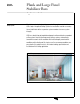
Technical Document Plank and Large Panel Stabilizer Bars Application Guide Plank and Large Panel Ceiling Systems Market demands for plank and large panel ceilings systems such as the USG® Logix™ Integrated Ceiling System has created the need for secondary lateral stabilization of the suspension system members to ensure system integrity.
Stabilizer Bars Introduction Features and Benefits – Versatile engineered stabilizer designs provide support, security and accessibility. – Factory-engineered solutions provide system rigidity in large module applications and offers quick installation reducing field labor time. – Available in numerous dimensions to facilitate fast delivery. – Durable galvanized steel construction. – Accessible stabilizer bars feature factory-engineered capture tabs prevent panel detachment and lip out.
Stabilizer Bars Description USG offers a variety of stabilizer bars to provide rigid support for ceiling suspension systems. Specially notched safety bars attach to the main tees and cross tees preventing the tee ends from spreading, and enhance the rigidity of ceiling modules.USG stabilizer bars are available in different sizes and options for various applications.
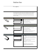
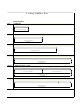
Standard Stabilizer Bars General Applications CC1530 309 Stabilizer Bar CC 15-30 CC2520 2 ft. 6 in. (30") center to center notch spacing 209 Stabilizer Bar CC 15-20 CC15-5 1 ft. 8 in. (20") center to center notch spacing 58 Stabilizer Bar CC 15-5 CC15-4-2 5 ft. (60") center to center notch spacing 48 Stabilizer Bar notched 28 on center 2 ft. (24") center to center notch spacing CC 15-4-2 CC15-4 4 ft. (48") center to center notch spacing 48 Stabilizer Bar CC 15-4 CC15-3 4 ft.
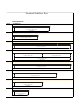
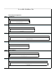
Locking Stabilizer Bars Seismic Applications SB12 SB12 SB24 18 Stabilizer Bar 1 ft. (12") center to center notch spacing 28 Stabilizer Bar SB24 SB36 2 ft. (24") center to center notch spacing 38 Stabilizer Bar SB36 SB48 3 ft. (36") center to center notch spacing 48 Stabilizer Bar SB48 SB48-24 4 ft. (48") center to center notch spacing 48 Stabilizer Bar notched 28 on center 2 ft. (24") center to center notch spacing SB48-24 SB60 SB60 2 ft. (24") center to center notch spacing 4 ft.
Accessible Stabilizer Bar Plank and Large Panel Applications ASB24 249 Stabilizer Bar ASB24 ASB30 2 ft. (24") center to center notch spacing 309 Stabilizer Bar ASB30 ASB48 2 ft. 6 in. (30") center to center notch spacing 489 Stabilizer Bar ASB48 ASB600 4 ft.
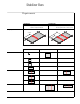
Stabilizer Bars Requirements 1 Stabilizer Bar Panels ≥ 609 2 Stabilizer Bars If panel length is ≥ 609 then one stabilizer is required at midpoint. If panel length is ≥ 96” then two stabilizer bars are required at the 1/3 and 2/3 points.
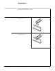
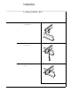
Installation Standard Stabilizer Bars 8 Application Guide Step 1 Apply the the stabilizer bar perpendicular to the perimeter tees. Step 2 Place the stabilizer bar aligning the notches onto the bulb of the tee.
Installation Locking Stabilizer Bars Step 1 Apply the the stabilizer bar perpendicular to the perimeter tees. Step 2 Fit stabilizer bar onto the tee bulbs through notches Step 3 Fold locking tabs to secure stabilizer bar in place.
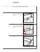
Installation Accessible Stabilizer Bars (ASB) 10 Application Guide Step 1 Towards each end of the ASB a stab tab is punched out of the lower leg. To ensure proper positioning the stab tab should be bent downwards. Step 2 Position the ASB on the back of the panel. There is a slot on either end of the bar that should align with the panel edge. Press firmly down on the bar until the stab tabs are fully engaged. Step 3 Engage the capture tabs on either end of the ASB.
Installation Accessible Stabilizer Bars Step 4 The capture tabs should not contact the paint or finish of the panel edge and should be pressed in as far as they can go to avoid interference with the suspension system. Step 5 If panel length is ≥ 969 then two stabilizer bars are required at the 1/3 and 2/3 points. Note: Install adjoining stabilizer bars at a slight offset to avoid interference with adjacent stabilizer bars. Step 6 Install the panel into the suspension system.
Installation Accessible Stabilizer Bars Step 7 The panel bar hooks over the bulb of the suspension system. Note: The bar does not seat on the top of the grid bulb, it captures the bulb laterally and keeps it in the proper relative position to the panel edge. Step 8 12 Application Guide After the panel is installed, the bulb tab may be turned towards the suspension system body to avoid interference when the adjacent panel is installed.
Installation Accessible Stabilizer Bars The maximum thickness of the material sitting on the suspension system flange is 7/89. 7/8" maximum thickness of material sitting on the suspension system flange The minimum is 3/89 3/8" minimum thickness of material sitting on the suspension system flange Note: The ASB works with full size grid profiles and does not work on the 19 small bulb profiles.
Installation Accessible Stabilizer Bars for USG True Wood Panels ™ A stabilizer bar is needed when installing certain USG True™ Wood panels, the Accessible Stabilizer Bar is to be used with the outer capture tab snipped off. Step 1 Step 2 14 Application Guide Determine number of stabilizer bars required. Snip off the outer capture tab.
Installation Accessible Stabilizer Bars for USG True Wood Panels Step 3 Center stabilizer bar so ends are flush with panel edge. For 2 x 8 panels, space stabilizer bars 24" o.c. CL Step 4 Fasten with 1/29 x 1/29 #12 screws. Step 5 Lower panel into grid opening, ensuring stabilizer bar engages with bulb of grid.
Product Information ICC Evaluation Service, Inc., See usg.com for the most Report Compliance up-to-date product information. Suspension systems manufactured by USG Interiors, Installation Inc., have been reviewed and Must be installed in compliance are approved by listing in with ASTM C636, ASTM E580, ICC-ES Evaluation Report 1222. CISCA, and standard industry Evaluation Reports are subject practices. to reexamination, revision and possible cancellation. Please Code Compliance refer to usgdesignstudio.