Translucents Canopies ™ Design and Installation Guide July, 2012
Design and Installation Guide Translucents Canopies from USG feature stand-alone ™ decorative elements that can be independently suspended or coupled together to achieve islands of color. Pages Overview 2 Elements Understand Your System Design Your System 4 Components Application Details Planning 7 Canopies Install Your System Angled Canopies Cable Heights For More Information Technical Service 800 USG.4YOU Web Site usg.
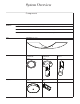
System Overview Elements Canopies Translucents™ Canopies are decorative elements that can be suspended as individual units or coupled together to achieve islands of color. Each canopy is pre-curved and comes with all the necessary installation hardware. The simplicity and minimalistic approach to these canopies provides aesthetics and simplified installation. Each Translucents Canopy (panel) is a composite of PETG or Acyllic that is embossed, laminated with fabric, or other decorative material.
System Overview Elements Vault Wave 3 Translucents™ Canopies
System Overview Components Terms and Definitions Canopies Descriptor for curved, independent, or groups of three-dimensional elements Elements Building blocks of Canopies (valleys, vaults or waves) used by a designer to define the space Panel Generic descriptor for the physical elements installed in the ceiling space Hardware Physical hanging and attachment devices for suspending the canopy panels Panel Formed Panel (Valley shown) Hardware 1/8" x 15' Stainless Steel Decorative Cable TRNCBL15 Ca
Application Details 5 Translucents™ Canopies
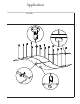
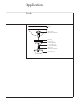
Application Details structure cable to structure attachment plate TRNCBLAP false ceiling decorative cable escutcheon TRNCBLESC 1/8" x 15' stainless steel decorative cable TRNCBL15 cable to panel attachment plate TRNCBLPA TRANSLUCENTS panel 6 Translucents™ Canopies
Installation Planning Job Site Conditions Building conditions: Building shall be enclosed with all windows and exterior doors in place and glazed, and the roof watertight. Interior temperature/humidity in building: Climatic conditions in areas to systems shall range from 60°F (16°C) to 85°F (29°C) and relative humidity of not more than 55% shall be maintained before installation of components.
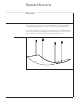
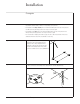
Installation Canopies Each panel will have 4 predrilled holes that will be used with the provided panel attachments plates. Layout marks should be made on the floor corresponding to each panel hole. – For installation of the Valley or Vault panel in a horizontal orientation (where the ends of the panels are level with each other) the hanger points are 13-1/2 by 34-1/2 inches apart.
Installation Canopies Figure 3 Figure 4 Install each structure attachment plate. Use appropriate anchors and for the mounting surface and follow the manufactures guidelines, each hanging point should have a hold a design load of 125 lbs with a safety factor of 2:1. Using an 8mm Allen Wrench, loosen the setscrew and insert the wire cable into the structure attachment clip.
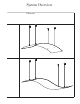
Installation Angled Canopies In an installation where the finished panels will be installed with one end higher than the other, it is important to note that the hanger wires in the long dimension will be closer together than a flat installation. Follow the steps below to determine the appropriate hanger wire spacing.
Installation Angled Canopies Figure 4 Using the framing square again, transfer these marks across and through the center control line. Figure 5 Measure and mark the finished hole locations 6-3/49 on both sides from the center control line. Figure 6 Plumb these marks up to the mounting surface or structure.
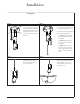
Installation Cable Heights Valley 35 1/2" 8 3/4" 4 3/8" finished ceiling height Vault 35 1/2" 2" 8 3/4" 6 3/4" finished ceiling height Barrel Vault Barrel Vault Install 30 7/8" 35 5/8" 30 7/8" 5/8" 17 1/2" difference finished ceiling height 12 Translucents™ Canopies
Installation Cable Heights Valley to Valley Vault to Valley Install 35 1/2" 33 1/4" 35 1/2" 17 1/2" difference finished ceiling height 5/8" Wave to Wave Wave to Wave Install 32 1/2" hanger cable 33" hanger cable 2" 14 3/4" 12 5/8" 5/8" 2" finished ceiling height Prouct Literature Data sheet: IC596 Notice We shall not be liable for incidental and consequential damages, directly or indirectly sustained, nor for any loss caused by application of these goods not in accordance with current printe