EM-408 Version 1.4.1 GPS Engine Board EM-408 Globalsat Technology Corporation 16F., No. 186, Jian-Yi Road, Chung-Ho City, Taipei Hsien 235, Taiwan Tel: 886-2-8226-3799/ Fax: 886-2-8226-3899 service@globalsat.com.tw www.globalsat.com.tw USGlobalSat, Inc. 14740 Yorba Court, Chino, CA 91710 Tel: 909.597.8525 / Fax: 909.597.8532 oem@usglobalsat.com www.usglobalsat.com Specifications are subject to be changed without notice.
EM-408 Version 1.4.1 1. Product Information Product Part I.D. EM-408 Product Description The EM-408 GPS engine board is low cost but maintains high reliability and accuracy making it an ideal choice for integration with OEM/ODM systems. The EM-408 features an integrated patch antenna for complete implementation.
EM-408 Sensitivity -159dBm Cold Start 42 seconds average Warm Start 38 seconds average Hot Start 8 second average Reacquisition 0.1 second average Accuracy Version 1.4.1 Position: 10 meters, 2D RMS 5 meters, 2D RMS, WAAS enabled Velocity: 0.1 ms Time: 1µs synchronized to GPS time Maximum Altitude 18,000 meters (60,000 feet) max Maximum Velocity 515 meter/second (1000 knots) max Maximum Acceleration 4G Datum WGS-84 Jerk Limit 20m/sec **3 Physical Characteristics Dimensions 1.4” x 1.
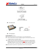
EM-408 Version 1.4.1 2. Technical Information Physical Characteristics Specifications are subject to be changed without notice.
EM-408 Version 1.4.1 Pin Assignment Pin Explanation ENABLE/DISABLE: On / Off VCC: (DC power input) This is the main DC supply for a 3.3V power module board. TX: This is the main transmit channel for outputting navigation and measurement data to user’s _ navigation software or user-written software. RX: This is the main receive channel for receiving software commands to the engine board from SiRfDemo software or from user-written software.
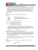
EM-408 Version 1.4.1 Mounting Recommended mounting methods: a. Use industrial grade double-sided foam tape. Place it on the bottom side of the engine board. b. A recessed cavity in your housing design with a foam pad to eliminate shifting or movement. c. Use provided mounting holes on the GPS engine board PCB. 3. Software Commands NMEA Output Command GGA-Global Positioning System Fixed Data Table B-2 contains the values for the following example: $GPGGA,161229.487,3723.2475,N,12158.3416,W,1,07,1.0,9.
EM-408 Version 1.4.1 Table B-3 Position Fix Indicator Value Description 0 1 Fix not available or invalid GPS SPS Mode, fix valid 2 Differential GPS, SPS Mode , fix valid 3 GPS PPS Mode, fix valid GLL-Geographic Position-Latitude/Longitude Table B-4 contains the values for the following example: $GPGLL,3723.2475,N,12158.3416,W,161229.487,A*2C Table B-4 GLL Data Format Name Example Units Message ID $GPGLL GLL protocol header Latitude N/S Indicator 3723.2475 n ddmm.
EM-408 VDOP 1.5 Checksum *33 Version 1.4.1 Vertical dilution of Precision 1. Satellite used in solution.
EM-408 Version 1.4.1 $GPRMC,161229.487,A,3723.2475,N,12158.3416,W,0.13,309.62,120598,,*10 Table B-9 RMC Data Format Name Example Message ID UTC Time $GPRMC 161229.487 RMC protocol header hhmmss.sss Status A A=data valid or V=data not valid Latitude 3723.2475 ddmm.mmmm N/S Indicator Longitude N 12158.3416 N=north or S=south dddmm.mmmm E/W Indicator W E=east or W=west Speed Over Ground 0.13 knots Course Over Ground Date 309.
EM-408 Version 1.4.1 ■ NMEA Input Command A.) Set Serial Port ID:100 Set PORTA parameters and protocol This command message is used to set the protocol (SiRF Binary, NMEA, or USER1) and/or the communication parameters (baud, data bits, stop bits, parity). Generally, this command is utilize to switch the GPS module back to SiRF Binary protocol mode, where an extensive message commands are readily available.
EM-408 available. Version 1.4.1 Y coordinate position INT32 Z coordinate position INT32 Clock offset of the receiver in Hz, Use 0 for last saved value if If this is unavailable, a default value of 75000 for GSP1, 95000 for GSP 1/LX is used. INT32 GPS Time Of Week UINT32 GPS Week Number UINT16 Week No and Time Of Week calculation from UTC time Number of channels to use.1-12.
EM-408 Version 1.4.1 D.) Query/Rate Control ID:103 Query standard NMEA message and/or set output rate This command is used to control standard NMEA data output messages: GGA, GLL, GSA, GSV, RMC, and VTG. Using this command message, standard NMEA message is polled once, or setup for periodic output. In addition, checksums may also be enable or disable contingent on receiving program requirements. NMEA message settings are stored in a battery-backed memory for each entry when the message is accepted.
EM-408 available. Version 1.4.1 Clock Offset of the receiver in Hz, use 0 for last saved value if If this is unavailable, a default value of 75000 for GSP1, 95000 for GSP1/LX is used. INT32 GPS Time Of Week UINT32 GPS Week Number UINT16 Number of channels to use. 1-12 UBYTE bit mask 0×01=Data Valid warm/hot starts=1 0×02=clear ephemeris warm start=1 0×04=clear memory. Cold start=1 UBYTE Example: Start using known position and time. $PSRF104,37.
EM-408 Name Example Units Version 1.4.1 Description Message ID $PSRF106 PSRF106 protocol header Datum 178 21= WGS84 178= Tokyo_Mean 179= Tokyo_Japan 180= Tokyo_Korea 181= Tpkyo_Okinawa Checksum *32 End of message termination * * * Specifications are subject to be changed without notice.