
User's Manual

3
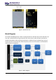
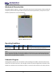
Hardware
The hardware is categorized into several parts. It discusses the interfacing, pinouts, and its
corresponding functions and diagrams. It also covers the parameters and standard values of the
board.
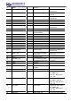
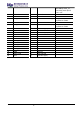
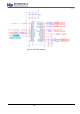
Interfaces
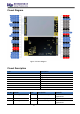
SPI Interface – SPI interface mainly provides for the HOST_SCK, HOST_MISO, HOST_MOSI,
HOST_CSN pins of the system connector. The SPI interface gives access to the configuration
register of SX1303 via a synchronous full-duplex protocol. Only the slave side is implemented.
USB Interface – The USB interface mainly provides for the USB_D+, USB_D- pins of the system
connector. The USB interface gives the access the configuration register of SX1303 via an
MCU STM32L412. Only the slave side is implemented.
UART and I2C interface – UP100 integrates a ZOE-M8Q GPS module which has UART and I2C
interface. The PINs on the golden finger provide a UART connection and an I2C connection,
which allows direct access to the GPS module. The PPS signal is not only connected to SX1303
internally but also connected to the golden finger which can be used by the host board.
GPS_PPS – UP100 includes the PPS input for received packets time-stamped and Fine
Timestamp.
RESET – UP100 SPI card includes the RESET active-high input signal to reset the radio
operations as specified by the SX1303 Specification. UP100 USB card’s RESET is controlled by
MCU.
Antenna RF Interface – The module have one RF interface over a standard UFL connector
with a characteristic impedance of 50Ω. The RF port supports both Tx and Rx, providing the
antenna interface.