Table Of Contents JSD-80 Cinema Sound Processor 1. Introduction .................................... 3 1.1 1.2 1.3 1.4 1.5 Safety notice Unpacking The JSD-80 Overview Technical Specifications Certifications 2. Installation ...................................... 9 2.1 2.2 7.4 7.5 7.6 7.7 7.8 7.9 System Hardware Mounting and Grounding System Cooling and Ventilation 8. “A” Chain Alignment .................... 23 8.1 8.2 8.3 8.4 8.5 3. Block Diagrams ............................ 10 3.1 3.2 3.3 3.
One Year Limited Warranty ★★★★★ USL, Inc. warrants that each product manufactured by it will be free from defects in material and workmanship under normal usage for a period of one (1) year after its purchase new from an authorized dealer. Our obligation under this warranty is limited to repairing or replacing any product or component which we are satisfied does not conform with the foregoing warranty and which is returned to our factory, freight paid, or serviced by one of our authorized contractors.
Section 1. Introduction Please read the entire manual before beginning your installation. • Keep Product Surfaces Clean and Dry. Disconnect the power cable from the power source before cleaning. Do not use liquid cleaners or aerosol cleaners. Use a damp cloth for cleaning. • Do Not Push Objects Into Opening of this Product. Never insert objects into the product through openings. • Do Not Operate In Wet or Damp Conditions. • Do Not Operate in an Explosive Atmosphere.
Le Résumé de la Sécurité général • Européen Examinez les précautions de la sécurité suivantes éviter la blessure et prévenir le dégât à ce produit. Éviter le risque potentiel, utilisez ce produit seulement comme a spécifié et seulement car le but a décrit dans le manuel d’instructions. Éviter Feu et Blessure Personnelle: • Utilisez le Câble du Pouvoir Correct. Utilisez seulement le câble du pouvoir fourni.
Allgemeine Sicherheit-Zusammenfassung Europäisch Überprüfen Sie die folgend SicherheitVorkehrungen, Verletzung zu vermeiden und Schaden zu diesem Produkt zu verhindern. Um potentielles Risiko zu vermeiden, benutzen Sie dieses Produkt nur als vorgeschrieben hat und nur denn der Zweck beschrieb in der Bedienungsanleitung. Um Feuer und Persönliche Verletzung zu vermeiden: • Benutzen Sie Korrektes Macht-Kabel. Benutzen Sie nur das Macht-Kabel, das bereitgestellt wurde.
1.2 Unpacking Unpack the unit carefully. If the container has been damaged, thoroughly inspect the equipment to make certain there is no hidden damage. File a claim immediately with the carrier if any damage is found. Also advise your dealer or the factory. The box should include the following items. If anything is missing, notify your dealer or the factory: 1.
1.4 Technical Specifications: Voltage adjustment: None f. Digital Input: Eight channels AES-EBU @ 32-96 kHz, 24-bit sample rate. Rack-mount chassis frame construction with plug-in modules accessible behind removable front panel. Signal Connections a. Standard 9-pin D-type female connectors for Projector 1, Projector 2, Mic, and RS-232 communications port. b. Standard 25-pin D-type female connectors for Analog eight-channel Input (Ext 1), Digital eight-channel (Ext 2) and automation I/O. c.
1.5 Declaration of Conformance, CE EC Declaration of Conformity Meets intent of Directive 89/336/EEC for Electromagnetic Compatibility and LowVoltage Directive 73/23/EEC for Product Safety.
Section 2: Installation 2.1 System Hardware Mounting and Grounding The JSD-80 is designed to mount in a standard 19" rack, and is two standard rack spaces (3-1/2") high. We recommend vented panels above and below whenever space permits. Mounting the unit immediately above a major heat-producing component (such as a power amplifier) is not recom- mended.
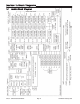
Section 3: Block Diagrams 3.1 Audio Block Diagram USL, Inc. JSD-80 Instruction Manual Page 10 3rd Edition.
3.2 Two-Channel Analog Input Block Diagram 3rd Edition. February, 2006 Page 11 USL, Inc.
Ext 2 Ext 1 3.3 Eight-Channel Input Block Diagram USL, Inc. JSD-80 Instruction Manual Page 12 3rd Edition.
3.4 Control Block Diagram 3rd Edition. February, 2006 Page 13 USL, Inc.
Section 4: System Modules 4.1 Input Module The Input Module contains the projector preamps plus Non-Sync, Auxiliary and Mic inputs. It also contains the bypass circuitry. Two high-power DSPs implement “A” type and “SR” noise reduction. A third DSP is used for the matrix decoder, slit eq analyzer and pink noise generator. Test points permit connection of an oscilloscope to align the film projector’s analog reader. LEDs indicate the presence of left, center, right and surround signals.
Section 5: Front Panel 8. Mic: for paging purposes 9. Mute: globally mutes all outputs 10. Level Indicator: also used for setting projector gains 11. Power Switch: when off, unit goes into bypass mode. 12. Bypass LED: indicates Bypass is active. 13. Power LEDs: indicates status of all internal supplies. 14. Main Fader Control: also used for setting projector gains. 5.1 Overview The front panel allows the operator to manually select formats and adjust the main fader.
Section 6: Back Panel 6.1 Rear Wiring Diagram USL, Inc. JSD-80 Instruction Manual Page 16 3rd Edition.
6.2 Back Panel Input Connections Projector Inputs The projector inputs are connected through standard 9-pin D-type connectors. (These connectors are included with the JSD-80). The pinout is: 1. In L+ 2. In L3. Shield 4. In R+ 5. In R6. Gnd 7. Reserved 8. Reserved 9. Gnd (An adapter board with setscrew terminals is available for solderless connections.) Non-Sync Inputs - Analog Two RCA connectors facilitate easy connection to standard CD players.
6.3 Back Panel Signal Output Connections The Automation common terminal is isolated from the system ground through an internal 10 Ohm resistor to minimize ground loop problems. Note: When wiring the automation inputs, use the Com terminal, not a ground terminal. Main Outputs These are the main processor outputs to connect to the power amplifiers. The outputs are balanced, and all have a corresponding ground terminal. Use two-conductor shielded cable for each channel.
Section 7: JSD-80 Interface Software 7.1 Installation Procedure the slider, holding down the left button and moving the mouse. Begin by placing the JSD-80 Laptop Interface Software CD into your CD-ROM drive. The software is compatible with Windows only. The installation program should start automatically within a few seconds. If it does not, you will need to run “Setup.exe” from the root directory of your CD-ROM drive. Either double click the “Setup.
7.5 Inputs Screen. There are two sections. The first section is the Preamp Controls section and contains buttons to select either Projector 1 or 2 level settings for the Left and Right preamps (with accompanying level indicators), Slit EQ & Mono EQ and the Slit EQ Analyzer screen which is dealt with in detail in Section 7.8. This tab is where the alignment is accomplished for the optical preamp (A Chain), and is vital for accurate optical performance.
an “up” or “down” arrow key and, for every push, the level will change .1 dB. Clicking on the button labeled “Flat” will restore all slider settings to the mid point and will warn you (if you accidentally hit it) before acting on the command. Note: If a channel should appear highlighted in red, it indicates that the channel has been muted on the Outputs Screen (see Section 7.7). 7.8 Slit EQ Analyzer Screen 7.7 Outputs Screen.
7.9 Creating, Saving and Loading Configuration Files Use the “New” command to create a custom configuration file starting with factory defaults. Use the “Save” or “Save As” command to save your custom configuration file to the hard disk. You may load a previously saved file by using the “File,” “Open” command and selecting the desired configuration file. If you are connected to the unit, the parameters will be automatically uploaded. (See also: System Restore From Personality Module, Section 10.4.
Section 8. “A” Chain Alignment 8.1 Preparing The Sound Head 1. Clean the soundhead optics thoroughly. If the film guide rollers are worn, replace them. Excessive side to side weave will cause insurmountable problems for the stereo circuitry and must be corrected prior to installation. 2. If the exciter lamp is old or blackened inside, replace it. Make sure the lamp is operating at a voltage greater than 60% of its rating.
Connect the shielding of the cable to the Chassis terminal (pin 3). Do not connect the shielding at the projector end. The D-9 connector should be plugged into the Projector 1 input of the JSD-80. 3. Film readers with active circuits, such as a Jaxlight line amplifier or a reverse scan reader, will require a ground connection at the reader.
will be necessary to reposition the film guide roller and realign the solar cell, so that both the 50% and 100% modulated tones match from channel to channel. When this fine alignment is not done, loud sounds (above 50% modulation) will be distorted and will leak into the surround channels. 9. Using the built-in SLIT EQ Analyzer adjust the SLIT EQ slider until the response is flat to 12 kHz +/- 1 dB. 8.3 Sum and Difference mode. No Oscilloscope required.
The graph below shows a reader with an azimuth error. The rising lower curve shows the phase difference between left and right channels. This is similar to a lissajous pattern on an oscilloscope where an ellipse indicates a poor alignment. The oscilloscope pattern is actually less accurate than the difference display. In the lissajous pattern, all the frequencies are added together so a phase difference at 20 kHz is less obvious.
right sliders outside the Preamp Calibration box to set the AUX level. 3. Connect a microphone to the DB-9 connector (pins 1+ and 2- with shield on 5). If the microphone is an electret type that requires 5 to 9 V DC you may use pin 7 on the DB-9 for that power (see Section 12). Click on the Inputs tab and select the MIC format. Adjust the left slide pot and both sides will change. 4. Select the Formats tab and select Mic. Click the appropriate radio button to direct the Mic to center or surround channels.
Note: When the computer is connected to and controlling the JSD-80, the front panel controls will not function, with the exception of the Mute button. To set the emergency digital fall back screen on the laptop interface, select “EXT 2” format. A box labelled “Digital Fallback” will appear. Simply select the emergency format desired. Selecting “EXT 2” will keep the processor in that format even though the audio may be muted.
Section 9 “B” Chain Alignment 9.1 Channel Configuration Selecting “File” in the menu bar will produce a drop down box. Click on “Input Configuration”. 9.3 Main Channels The processor supports either five screen channels or “Ex” back surround channels but not both. Select the appropriate configuration and click “OK”. Note: This configuration will affect the equalizer and format panels. 9.2 Headroom Settings Selecting “File” on the menu bar will produce a dropdown box. Click on “Headroom Adjustment”.
the generator (e.g., center and subwoofer channels). To use the internal JSD-80 REAL TIME ANALYZER, connect the microphone to the MIC input on the JSD-80. (See Section 12 for connector pin-outs.) With the pink noise generator turned on and the equalizer screen displayed on the laptop, select the inputs screen. Note that the MIC input is selected. The auditorium microphone can be adjusted by using the MIC gain slider. Double click on the REAL TIME ANALYZER screen. A new window will open.
10 dB ABOVE the horizontal display of the center channel on the REAL TIME ANALYZER. 9.5 Optical Subwoofer 1. Once the subwoofer channel is equalized and the level set, it is time to trim the optical subwoofer parameters. 2. Turn off the pink noise generator. 3. Thread a pink noise loop Cat 69 P or equivalent on the projector and select mono. 4. Set the optical subwoofer frequency to 50 or 60 Hz. 5. Using the auditorium microphone note the level of the pink noise from the center channel. 6.
unit allowing you to make more modifications if needed. Choosing “Do Not Save” will disconnect from the unit and disregard all changes made for the current session. The unit will continue to retain the current settings until power is removed then the previous configuration will be used. Checking the “Save to Personality Module” will save a backup of the entire unit configuration to the unit’s Personality Module.
Section 10: Other Options 10.1 Preset Format Levels figuration saved to the Personality Module (1). If the control card is the module that has failed you will need to remove the Personality Module from it and insert it into the replacement control card from USL. If the input or output card has failed, you simply need to replace the failed one with a new module from USL. Once the replacement module is installed, you will hold down the restore button (4) as you power up the system.
The MONO, STEREO A, STEREO SR buttons can be configured with the following noise reduction options: “None,” A Type, SR Type. The same buttons can also be configured with the following matrix decoding options: “5.1 Stereo,” “2.0 Stereo,” or “Mono.” The 5.1 stereo option is the default setting. The 2.0 stereo option is for either Left/Right stereo or Center/Surround systems. The EXT 2 button can be configured either for “AES-EBU” (Digital) or “Analog” inputs. 10.
Section 11: Troubleshooting PROBLEM SOUND SYSTEM DOES NOT WORK and no LEDs are lit on the Front Panel. CHECK SOLUTION Power source Reset circuit breaker or replace fuse. Power cord Make sure power cord is firmly seated. Power supply fuse Replace Fuse - SLO BLO 500 mA, 250 V Power amplifiers Make sure amplifiers are operating and volume controls are up. Change-over Switch change-over to operating projector. LED lights on the Input Module indicate which projector is in use.
PROBLEM SOUND IS DISTORTED CHECK SOLUTION Power amplifier or speaker Try to determine if distortion is in one or all channels. If distortion is one channel, exchange power amplifiers or speaker lines to locate problem. Press several format buttons Try to determine if one or all formats are distorted. Try NON/SYNC MUSIC If MUSIC is not distorted, the problem is in the input module or the SOLAR CELL alignment.
PROBLEM STEREO MODE DIALOG IS LEAKING INTO THE SURROUNDS STEREO MODE SURROUNDS ARE EXTREMELY LOW CHECK SOLUTION Soundhead azimuth alignment and/or preamp level and high frequency boost settings Re-adjust soundhead azimuth and reset preamp levels and high frequency boost with test film. Soundhead guide rollers Make sure the soundhead guide rollers are not loose and do not have any end play. Some rollers are spring-loaded on one side. Make sure the fixed side is not loose.
Section 12: Appendix Connector Pinouts RS232 (DB-9F) 1. 2. 3. 4. 5. 6. 7. 8. 9. Reserved TXD Transmit Data RXD Receive Data Reserved Signal Ground Reserved CTS Clear To Send RTS Request To Send +5 V for Bluetooth Adaptor 1. 2. 3. 4. 5. 6. 7. 8. 9. 10. 11. 12. 13. 14. 15. 16. 17. 18. 19. 20. 21. 22. 23. 24. 25.
Section 13: Installation Check List B CHAIN ALIGNMENT 1. Select Lc/Rc or Bsl/Bsr channel operating mode in the File menu of the Interface Software. 2. Set Headroom (26 dB is normal). Older speaker systems may require 29 dB. 3 Equalize front channels and set SPL levels (85 dB) using the Equalizer screen. 4 Equalize surround channels and set SPL levels (82 dB) using the Equalizer screen.