
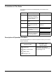
Specifications
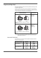

Part Names and Functions
1-2 OPERATION GUIDE
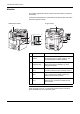
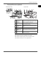
Machine
This chapter explains the names of parts when the machine is used as a
fax machine.
For the parts required when functions other than FAX are used, refer to the
machine’s Operation Guide.
IMPORTANT: You cannot automatically receive a fax when the main
power switch is turned off. To receive faxes with the power turned off,
press the Power key on the operation panel.
2
3
6
4
11
2
3
6
4
5
5
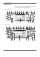
30/40/50 ppm model 25 ppm model
1 Operation panel Perform the fax operation with this panel.
2 Main power
switch
Set this switch to the ON (|) side when
performing the fax or copier operation. The
touch panel lights to enable operation.
3 MP (Multi
Purpose) tray
Set the paper in this tray when using a type of
paper other than the cassette (e.g., when
using special paper).
4 LINE connector
(L1)
Connect the modular cord for the telephone
line to this connector. This connector is Port 1.
5 LINE connector
(L2)
If you install the Dual FAX option, you can use
Port 2. Connect the modular cord for the
telephone line to this connector.
6 TEL connector
(T1)
When using a commercially available
telephone set, connect the modular cord to
this connector.