GE AccessSmart 313 Last Update July 6, 2005 GE AccessSmart 313 Last Update July 6, 2005 Table of Contents 1. IMPORTANT SAFTY INSTRUCTIONS Page 4 2. INTRODUCTION 2.1 IDENTIFYING SUPPLIED PARTS 2.2 INTRODUCTION 2.3 FEATURES 2.4 SPECIFICATIONS Page 6 Page 6 Page 6 Page 6 Page 7 3. PRODUCT OVERVIEW 3.1 FUNCTIONS 3.2 PRODUCT EXPLANATION 3.2.1 FRONT PANEL DESCRIPTION 3.2.2 CONNECTOR LAYOUT 3.2.3 WIRE COLOR TABLE OF THE GE314 Page 8 Page 8 Page10 Page10 Page11 Page11 4. INSTALLATION TIPS & CHECK POINT 4.
GE AccessSmart 313 Last Update July 6, 2005 7. BASIC SETTINGS 7.1 INITIALIZATION OF GE314 7.2 HOW TO ENTER THE SETUP MENU 7.3 LANGUAGE SETTING 7.4 DATE/TIME SETTING 7.5 ID REGISTRATION Page 22 Page 22 Page 22 Page 23 Page 23 Page 24 GE AccessSmart 313 Last Update July 6, 2005 1. IMPORTANT SAFETY INSTRUCTIONS To prevent injuries to persons and damages to property, please read all instructions and follow them whenever you deal with this product. 8. OPERATION 8.1 NORMAL OPERATION 8.
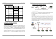
GE AccessSmart 313 Last Update July 6, 2005 NOTICE GE AccessSmart 313 Last Update July 6, 2005 2. INTRODUCTION Please contact a designated service center or the outlet at which the product was purchased when 2.1 IDENTIFYING SUPPLIED PARTS A. Any liquid has been spilt or sprayed onto the product. In this case, cut the power off first. B. The product seems to be operating abnormally. Please unpack and check the contents of the box (Optional accessories, if purchased, may be included in the C.
GE AccessSmart 313 z z z z z Last Update July 6, 2005 10 Holiday Schedules, 100 holidays each Operating Mode Selectable for Individual ID (Proximity/PIN Only Mode, Proximity + Password Mode) Time Schedule Applied to Individual ID, Input Port, Output Port and Reader Mode Multiple Master ID Registration 3 LED Indicators and Beeper for the System Status GE AccessSmart 313 Last Update July 6, 2005 3. PRODUCT OVERVIEW 3.
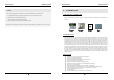
GE AccessSmart 313 Example: A. Last Update July 6, 2005 Holiday schedule 01 linked to time schedule 01, Holiday schedule 02 linked to time schedule 02 B. Holiday schedule 02 linked to time schedule 01, GE AccessSmart 313 Last Update July 6, 2005 3.2 PRODUCT EXPLANATION 3.2.1 FRONT PANEL DESCRIPTION Holiday schedule 01 linked to time schedule 03 LCD Forced Door Open Alarm When the door is opened by force, the door contact sensor will be activated.
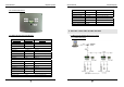
GE AccessSmart 313 Last Update July 6, 2005 3.2.2 CONNECTOR LAYOUT GE AccessSmart 313 Last Update July 6, 2005 Door RELAY(COM) COM(1) Green wire with white stripe Door RELAY(NO) NO(1) White wire with red stripe Alarm RELAY(NC) NC(2) Yellow wire with red stripe Alarm RELAY(COM) COM(2) Brown wire with white stripe Alarm RELAY(NO) NO(2) Blue wire with white stripe Exit Button EXIT Orange wire Door Sensor CONTACT Purple wire CNN-5: TCP/IP RJ45 CONNECTOR 4.
GE AccessSmart 313 Last Update July 6, 2005 4.1.2 CABLE SELECTION TABLE Reference ① GE AccessSmart 313 Last Update July 6, 2005 4.2.
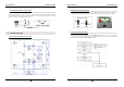
GE AccessSmart 313 Last Update July 6, 2005 4.2.4 REVERSE DIODE CONNECTION If you connect an inductor (Door Locks or Alarm device) to the output relays, there will be a high surge voltage created while the inductor is turning on and off. If you do not connect reverse diode, the surge voltage will transfer and damage to the electronic circuit of the controller. It is strongly recommended to add a reverse diode between the inductor coils to absorb this surge voltage. Figure: Reverse Diode connection 5.
GE AccessSmart 313 Last Update July 6, 2005 5.4 WALL MOUNT INSTALLATION z z z z z 6. GE AccessSmart 313 Last Update July 6, 2005 6.3 OUTPUT CONNECTION Position the Wall Mount to the location where you install the unit and mark 4 x drilling position. Drill 632 holes at least 4 mounting point. Drill 1/2” hole on the center of Wall Mount. Using 4 screws, install the Wall Mount to the proper location. Take out the cable through the center hole.
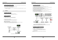
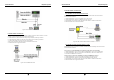
GE AccessSmart 313 Last Update July 6, 2005 GE AccessSmart 313 Last Update July 6, 2005 6.6 RS-485 PORT CONNECTION 6.6.1 RS-485 CONNECTION(SINGLE UNIT) RS485/RS232 converter is required to use RS485 communication between the GE313 and a host PC. Please follow the instructions. 1. Connect RS485-RTX(+), Grey wire to RS485-A port of the converter. 2. Connect RS485-RTX(-), Blue wire to RS485-B port of the converter. 3.
GE AccessSmart 313 Last Update July 6, 2005 GE AccessSmart 313 7. Last Update July 6, 2005 BASIC SETTINGS 7.1 INITIALIZATION OF GE313 After the all installation and connections are completed, press and hold the Initialize button and put the power (+12V DC) to GE313. The LCD will first display “Initialize OK? 0:No 1:Yes”. Press <1> key if you want to initialize the system.
GE AccessSmart 313 Last Update July 6, 2005 GE AccessSmart 313 Last Update July 6, 2005 7.5 ID REGISTRATION You can register the User ID into the GE313. Select [F4 SETUP MENU] -> [REGISTRATION] and follow the steps below. 7.3 LANGUAGE SETTING 1. Registration by Card Select [LANGUAGE] in the [F2 SETUP MENU] then press key to select the LANGUAGE. Please follow the steps below for LANGUAGE setting and following procedure is for selecting CHINESE. 2. Registration by Key 7.
GE AccessSmart 313 Last Update July 6, 2005 4. TA: TA is the Time Schedule code (‘00’ ~ ‘10’) for the Reader#1 (Built-in Reader). When you present the card to the Reader#1, the cardholder is only allowed the access of the door during the Time intervals of the Time Schedule code entered to TA. To setup the Time intervals for each Time Schedule code, refer to the Time Schedule Setup on the [F5 SETUP MENU].
GE AccessSmart 313 9. Last Update July 6, 2005 GE AccessSmart 313 Last Update July 6, 2005 9.1 F1 SETUP MENU SETTING CHANGES ☞. To setup or to change the GE313 settings, you have to enter the SETUP MENU first. To do so, press <0> key eight times (Default Master ID ‘00000000’) and key from the Keypad. You now entered to the SETUP MENU. There are 8 SETUP MENU and you first get into [F1 SETUP MENU]. You can move to another SETUP MENU by pressing key to key button.
GE AccessSmart 313 Last Update July 6, 2005 9.1.2 INPUT TEST GE AccessSmart 313 Last Update July 6, 2005 9.1.5 KEYPAD TEST ☞. LCD will display all keys of the unit. Press each key from the keypad one by one, the depressed key will disappear from the LCD. Note that ENT key is “#” and ESC key is “*” on the LCD. ☞. The 5digit shows the input status and “0” indicates that the input port is open circuit and “1” indicates that the input port is short circuit to ground level. 9.1.6 READER TEST 9.1.
GE AccessSmart 313 Last Update July 6, 2005 GE AccessSmart 313 Last Update July 6, 2005 9.2 F2 SETUP MENU 9.1.8 COMMUNICATION TEST ☞. Before this communication test, connect RS232-RX and RS232-TX wires together. ☞. This test is a loop test and GE313 sends a character to RS232-TX and check whether the RS232-RX receive the same character or not. If you have an error, contact manufacturer for technical support.
GE AccessSmart 313 Last Update July 6, 2005 9.2.1 LANGUAGE GE AccessSmart 313 Last Update July 6, 2005 9.2.4 READER#2 MODE READER#2 MODE setting is the same as 9.2.3 READER#1 MODE setting. Note: READER#2 is an external Exit reader of the unit. ID(PIN) ONLY: The door is accessible by just presenting the proximity card(or Press the ID Number). ID+P/W: The door is accessible by presenting a card and Password. 9.2.5 READER#1 PIN INPUT ☞. The default Language is in ENGLISH. ☞.
GE AccessSmart 313 Last Update July 6, 2005 GE AccessSmart 313 Last Update July 6, 2005 9.3 F3 SETUP MENU 9.2.8 BAUD RATE SETTING ☞. GE313 supports 9600, 19200, 38400 and 57600bps of Baud Rate and default Baud Rate is 9600bps. Wrong Baud Rate setting will cause communication error and you have to set same Baud Rate for the same communication network.
GE AccessSmart 313 Last Update July 6, 2005 GE AccessSmart 313 Last Update July 6, 2005 9.3.3 TIME UNIT SETTING 9.3.1 EVENT MEMORY ☞. You can select whether you will use event memory or not. When you select USE and in case of an event memory, GE313 generates an error message and keeps all events stored in the memory. When you select UNUSE, GE313 will not generate an error and new event overwrite into the event buffers. If you use GE313 for standalone (just for door access), select UNUSE. 9.3.
GE AccessSmart 313 Last Update July 6, 2005 9.3.5 ANTI-PASS BACK MODE GE AccessSmart 313 Last Update July 6, 2005 ☞. This is the function to use GE313 as a Reader and sends 26bit Wiegand Output through two TTL output ports. Press key and select USE by pressing <4> or <6> key then press key for setting. UNUSE: Normal TTL outputs will be activated. USE: 26bit Wiegand output will be generated through TTL1 and TTL2 port.
GE AccessSmart 313 Last Update July 6, 2005 9.4 F4 SETUP MENU GE AccessSmart 313 Last Update July 6, 2005 2. Registration by Keypad 1. Scanning… The reader is waiting for the ID number to be registered. The card number will appear with a beep sound when you present the card. ID number is 8digit number. 2. ID: ID number consists of 4~8 digit. Enter 4~8digit ID number (PIN) and press key on the field. 3.
GE AccessSmart 313 Last Update July 6, 2005 7. MA: MA is the Reader#1 (Built-in Reader) Operating Mode for the cardholder. If you put ‘1’ for MA, GE AccessSmart 313 Last Update July 6, 2005 9.4.3 ID LIST Reader#1 is always operating on RF Only Mode. ‘0’ – System Operating Mode [F2 SETUP MENU]Æ [READER#1 MODE] ‘1’ – ID Only Mode ‘2’ – ID + Password Mode 8. MB: MB is the Reader#2 (Exit Reader) Operating Mode for the cardholder. If you put ‘1’ for MB, Reader#2 is always operating on RF Only Mode.
GE AccessSmart 313 Last Update July 6, 2005 GE AccessSmart 313 Last Update July 6, 2005 9.5 F5 SETUP MENU 9.4.5 ID COUNT ☞. This menu displays the total number of registered user ID. It automatically counts when you register or delete user IDs. The LCD shows total 123 user IDs registered in the memory. 9.4.6 EVENT COUNT ☞. This menu displays the total number of Event stored in the memory. It automatically increases the count when the Event is stored in the memory.
GE AccessSmart 313 Last Update July 6, 2005 ☞. There are 10 Time Schedule Code available for the users. T/S Code “00” is a default and allows the access for all users for all the time. (Access is granted 24 hours per day) The user can program the Time Schedule Code from “01” to “10”. Each Time Schedule Code has 8 programmable days (Sun, Mon, Tue, Wed, Thu, Fri, Sat and Holiday) and each day has 5 Time Intervals. (Shift time or Accessible time zone) ☞.
GE AccessSmart 313 Last Update July 6, 2005 GE AccessSmart 313 Last Update July 6, 2005 * Default Output Setting for Input Sources 9.
GE AccessSmart 313 Last Update July 6, 2005 9.6.7 OUTPUT TIME SCHEDULE SETTING GE AccessSmart 313 Last Update July 6, 2005 9.7 F7 SETUP MENU ☞. You can link a T/S Code to each Output. The default T/S Code is “00” which means no T/S is applied to the Outputs. This setting is very useful when you want to open the door for a Time Interval. Press key to link a T/S Code to the Output then enter 2digit T/S Code for each Output.
GE AccessSmart 313 Last Update July 6, 2005 * Default Output Setting for Input Circumstance GE AccessSmart 313 Last Update July 6, 2005 9.7.2 OUTPUT SETTING FOR READER#1 ID OK LEVEL 2 Door Alarm Relay Relay (DR) (AR) [1] Reader#1 ID OK LV1 03 [2] Reader#1 ID OK LV2 This Output Time is applied for the users registered with Level#2 output. TTL#1 TTL#2 Buzzer (T1) (T2) (BZ) 00 00 00 00 This Output Time is applied for the users registered with Level#3 output. 05 00 00 00 00 9.7.
GE AccessSmart 313 Last Update July 6, 2005 9.8 F8 SETUP MENU GE AccessSmart 313 Last Update July 6, 2005 9.8.2 EVENT CLEAR ☞. When the event memory is full or when you want to change ID COUNT, you can clear the event memory in this menu. Press key then press <1> key to clear event memory or <0> key to cancel the operation. CAUTION: Before you clear the events, make sure that the stored events is not necessary to upload to the host PC otherwise you may lose important data. 9.8.3 ID CLEAR ☞.
GE AccessSmart 313 Last Update July 6, 2005 9.8.5 TIME SCHEDULE CLEAR GE AccessSmart 313 Last Update July 6, 2005 APPENDIX A. THE RELATION BETWEEN INPUT AND OUTPUT (DEFAULT) * Default Output Setting for Input Sources ☞. When you want to delete all Time Schedules (01~10), all Holiday schedules(01~10), Holiday code, Reader#1 Mode T/S code and Reader#1 Mode T/S code, you can clear them from the memory. Press key and press the <1> key to clear all T/S or <0> key to cancel the operation.
GE AccessSmart 313 Last Update July 6, 2005 * Default Output Setting for Input Circumstance Door Alarm Relay (DR) (AR) [1] Reader#1 ID OK LV1 03 [2] Reader#1 ID OK LV2 [3] Reader#1 ID OK LV3 TTL#1 TTL#2 Buzzer (T1) (T2) (BZ) 00 00 00 00 05 00 00 00 00 05 00 00 00 00 [4] Reader#1 ID OK LV4 05 00 00 00 00 [5] Reader#1 ID Error 00 03 00 00 00 [6] Reader#1 T/S Error 00 03 00 00 00 [7] Reader#1 APB Error 00 03 00 00 00 [8] Reader#2 ID OK LV1 03 00 00 00 0
GE AccessSmart 313 Last Update July 6, 2005 ☞ No problem with accessing by card, but cannot access with the PIN input. Cause Solution An error in Setup or possible component defect. 1. Check whether a beep sound is generated when you press a key. GE AccessSmart 313 Last Update July 6, 2005 ☞ “SCHEDULE ERROR” message shows when RFID card is read. Cause Error in RFID card registration, time schedule setting or the system itself. Solution 1.
GE AccessSmart 313 Last Update July 6, 2005 ☞ The controller does not communicate with the Host-PC. Cause A defective cable is used, errors in wiring, an error in setting COMM ID of the controller, or damage on GE AccessSmart 313 Last Update July 6, 2005 FCC REGISTRATION INFORMATION the communication port (either on PC side or on the controller side). Solution 1. Please check the settings of the application S/W and the controller. - Check if the controller’s COMM ID is listed on the application S/W.