
User's Manual


GE AccessSmart 313 Last Update July 6, 2005
7
z 10 Holiday Schedules, 100 holidays each
z Operating Mode Selectable for Individual ID (Proximity/PIN Only Mode, Proximity + Password Mode)
z Time Schedule Applied to Individual ID, Input Port, Output Port and Reader Mode
z Multiple Master ID Registration
z 3 LED Indicators and Beeper for the System Status
2.4 SPECIFICATIONS
CPU 8 bit and 16bit Dual Microprocessors
Memory Program Memory: 2M bit ROM
Data Memory: 4M bit FLASH memory
Card Holder
Event Buffer
10,000 Users
20,000 Event Buffers
Operating Mode Operating mode can be programmed for Individual ID
- Proximity Card Only or PIN Only Mode
- Proximity Card and Password Mode
Reader Port 1 Internal and 1 External Reader Port
Read Range Up to 4” (10cm) with IDC170 Clamshell Card
Reader Data Format Standard IDC 26 bit Wiegand Format
8 bit Burst Format for Keypad reader
Communication port RS232/RS485(up to 256 channels) Address Selectable
9600(Default), 19200, 38400, 57600bps Communication Speed
Input/Output 4 Input Ports, Rating DC12V/ 20mA max.
2 Relay Outputs, DC12V~24V/ FORM-C Relay 2A max.
2 TTL Outputs, DC0 ~5V/ 20mA max.
Keypad 24 keys with Back lighting (Sky Blue)
- 10 Numeric Keys
- 2 Control Keys
- 12 Function Keys
Self Diagnostic Yes
Reset Power On Reset and Watch-dog Timer Reset
Operating Status 3 LED (Red, Green, Yellow) indicators, Beeper
Weight 1.5 lbs (675g)
Dimensions 7.56” x 6.42” x 1.97” (192mm x163mm x50mm)
LCD Display Module 128 x 64 dots, 2.85” x 1.56”(72.5mm x 39.5mm) View Area
Power DC 12V±10%, 400mA max.
Operating Environment 32°F ~ 149°F (0°C ~ +65°C), 0 ~ 90% Humidity None Condensing
Storage Environment -40°F ~ 158°F (-40 ~+70℃℃), 0 ~ 90% Humidity None Condensing
Mount Wall Mount or Electrical Gang Box Mount (U.S. and European/Asian)
Color Silver and Dark Gray Color
Optional
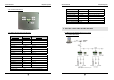
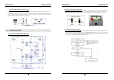
TCP/IP Module (Internal)
Connection
IIM7100A Internal Mounting Module for TCP/IP Communication
RJ45 Socket
GE AccessSmart 313 Last Update July 6, 2005
8
3. PRODUCT OVERVIEW
3.1 FUNCTIONS
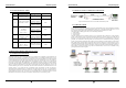
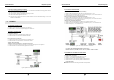
Stand-Alone Operation
The GE313 is capable of having 2 readers (1 Door Control). The unit receives card ID numbers from the
proximity readers and determines whether or not to unlock the door. When an input signal is entered, for
example from a Sensor activated or an Exit button pressed, the controller generates and logs an appropriate
response by input signals. All events are stored into the memory buffers and sent to the host computer. The
access controller is a true stand-alone device that, in the event of malfunction, will not affect other units when
used in conjunction with one another.
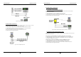
Operation with Host Computer
All event transactions can be managed via the host computer. The data transmitted from the controller can be
displayed and stored on the host PC.
Keypad
If the GE313 is not connected to a host PC, the integrated keypad and LCD display module can also be used
for the entire programming process.
Input/Output
The GE313 has 4 built-in inputs and 4 outputs (2 relay outputs and 2 TTL outputs) which can be used to
manipulate a wide variety of controls.
Time Schedule Setup
You can program 10 time schedules and apply one time schedule to each User. Each time schedule has 8
different time zones from Monday-Sunday (7 time zones) and one holiday. Each time zone has 5 different
time codes so you can program 5 different time codes to each day. You can also program time schedules for
individual inputs and outputs. Note that the time schedule for input is activated time code for input device so
that the input is activated during the time code on this time schedule. Each time schedule is linked to one
holiday schedule and this linked holiday only validates to the holiday time code of the time schedule.
Holiday Schedule Setup
Excepting Sunday, you can program 100 holidays to one holiday schedule. Each holiday schedule is linked to
one time schedule which has a time code for holidays. You can program all holidays to a holiday schedule
and the time code for holidays is programmed to the holiday time zone of time schedule.