
User's Manual


GE AccessSmart 313 Last Update July 6, 2005
11
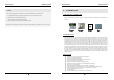
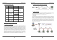
3.2.2 CONNECTOR LAYOUT
Figure: Connector Layout
3.2.3 WIRE COLOR TABLE OF THE GE313
I/O PORT NAME SIGNAL NAME WIRE COLOR
CNN-1: POWER
Main Power (+12V) +12V Red wire
Power Ground 0V Black wire
CNN-2:COMMUNICATION
RS485-RTX(+) RS485-A(+) Gray wire
RS485-RTX(-) RS485-B(-) Blue wire
RS232-TX TXD Red wire with white stripe
RS232-RX RXD Black wire with white stripe
RS232-GND GND Black wire
CNN-3: INPUT/OUTPUT
TTL OUTPUT #1 TTL#1, WD0 Brown wire
TTL OUTPUT #2 TTL#2, WD1 Yellow wire
Aux Input #1 IN#1 Pink wire
Aux Input #2 IN#2 Cyan wire
Wiegand DATA 0 DATA-0 Green wire
Wiegand DATA 1 DATA-1 White wire
CNN-4: INPUT/OUTPUT
Door RELAY(NC) NC(1) Gray wire with white stripe
GE AccessSmart 313 Last Update July 6, 2005
12
Door RELAY(COM) COM(1) Green wire with white stripe
Door RELAY(NO) NO(1) White wire with red stripe
Alarm RELAY(NC) NC(2) Yellow wire with red stripe
Alarm RELAY(COM) COM(2) Brown wire with white stripe
Alarm RELAY(NO) NO(2) Blue wire with white stripe
Exit Button EXIT Orange wire
Door Sensor CONTACT Purple wire
CNN-5: TCP/IP RJ45 CONNECTOR
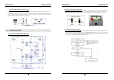
4. INSTALLATION TIPS & CHECK POINT
4.1 CHECK POINT BEFORE THE INSTALLATION
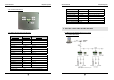
4.1.1 CABLE SELECTION
Figure: System Installation Layout