
User's Manual


GE AccessSmart 313 Last Update July 6, 2005
13
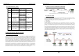
4.1.2 CABLE SELECTION TABLE
Reference Description Cable Specification Maximum Distance
①
GE313 Power (DC12V)
DC Power -> GE313
Belden #9409, 18 AWG
2 conductor, unshielded
30m
Belden #9512, 22 AWG
4 conductor, shielded
②
+
Reader (Power and Data)
Exit Reader -> GE616
Belden #9514, 22 AWG
8 conductor, shielded
150m
Belden #9512, 22 AWG
4 conductor, shielded
③
Door Contact
Exit Button
Sensor Input
Input -> GE313
Belden #9514, 22 AWG
8 conductor, shielded
300m
④
Door Lock, Alarm Device
Lock (Alarm) -> GE313
Belden #9409, 18AWG
2 conductor, unshielded
300m
⑤
RS232 Cable
Converter -> Host P.C.
Belden #9829, 24 AWG
2-twisted pair, shielded
15m
⑥
RS485 Cable
GE313 -> GE313
GE313 -> Converter
Belden #9829, 24 AWG
2-twisted pair, shielded
1,200m
+
: Need thicker wire if you connect the reader with high current consumption.
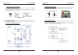
4.2 CHECK POINT DURING THE INSTALLATION
4.2.1 TERMINATION RESISTOR
Termination resistors are used to match impedance of the network to the impedance of the transmission line
being used. When impedance is mismatched, the transmitted signal is not completely absorbed by the receiver
and a portion of signal is reflected back into the transmission line. The decision whether or not to use termination
resistors should be based on the cable length and data rate used by the communication system. For example, if
you use 9,600 baud rate and 1,200m length of cable, the propagation velocity of cable is 0.66 x speed of light
(This value is specified by the cable manufacturer), if we assume the reflections will damp out in three round trip
up and down the cable length, the transmitted signal will stabilize 18.6us after the leading edge of a bit. Since the
data bit is captured in the middle of the bit which is approximately 52us after the leading edge of a bit. The
reflection stabilizing time 18.6us is much before the center of the bit therefore the termination resistors are not
required. However, if you install the cable to maximum length, the impedance of cable and network is
mismatched and the transmitted signal is overlapped by the reflected signal. In this case, it is recommended to
add termination resistors to the end of the receiver lines. A 120Ω resistor can be used for termination resistor in
parallel between the receiver lines “A” and “B” for 2 wires RS485 system. A termination resistor of less than
90Ω should not be used and no more than 2 terminations should be used in one networking system.
GE AccessSmart 313 Last Update July 6, 2005
14
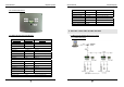
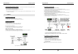
4.2.2 HOW TO CONNECT TERMINATION RESISTORS
Figure: Termination resistors for 2 wire RS485 communication system
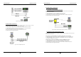
4.2.3 GROUND SYSTEM
We recommend to using proper grounding system of the communication cable. The best method for grounding
system is to put the shield wire of the communication cable to the 1
st
class earth grounding; however it is not so
easy to bring the earth ground to the communication cable and also the installation cost is raised.
There will be three grounding point where you can find during installation;
1) Earth Ground
2) Chassis Ground
3) Power Ground
The most important point for grounding system is not to connect both ends of shield wires to the grounding
system; in this case there will be a current flow through the shield wire when the voltage level of both ends of
shield wire is not equal and this current flow will create noise and interfere to communications. For the good
grounding, we recommend to connecting ONLY one end of shield wire of communication cable to grounding
system; If you find earth ground nearby, then connect one end of shield wire to earth ground; If you do not have
earth ground nearby, then find chassis ground and connect one end of shield wire to chassis ground; If you do
not find both earth ground and chassis ground, then connect one end of shield wire to power ground. (GND of
GE313) Note that if the chassis ground is not properly connected to the earth and floated from the ground level,
then grounding to the chassis ground will give the worst communication; in this case we recommend to using
power ground instead of chassis ground.
Figure: Grounding system