
User's Manual


GE AccessSmart 313 Last Update July 6, 2005
15
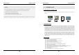
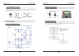
4.2.4 REVERSE DIODE CONNECTION
If you connect an inductor (Door Locks or Alarm device) to the output relays, there will be a high surge voltage
created while the inductor is turning on and off. If you do not connect reverse diode, the surge voltage will
transfer and damage to the electronic circuit of the controller. It is strongly recommended to add a reverse diode
between the inductor coils to absorb this surge voltage.
Figure: Reverse Diode connection
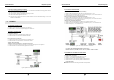
5. INSTALLATION
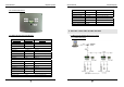
5.1 WALL MOUNT DRAWING (Unit: mm)
Figure: Wall Mount Layout
GE AccessSmart 313 Last Update July 6, 2005
16
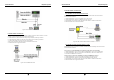
5.2 BACKUP BATTERY SWITCH
GE313 has a switch for the backup battery connection, which remains open circuit to prevent any current
consumption of the backup battery (Figure: Switch setting). Before the GE313 operation, it needs to be
connected so that the backup battery can retain the serial RTC(Date and Time data) during power failure.
Figure: SWITCH SETTING Figure: SWITCH LOCATION
5.3 SYSTEM INITIALIZATION
After the all installation and connections are completed, press and hold the Initialize button and put the power
(+12V DC) to GE313. The LCD will first display “Initialize OK? 0:No 1:Yes”. Press <1> key if you want to
initialize the system. After all Initialization process is completed, the system is operating on normal mode and
the LCD displays “GE Security, GE313 [F1], Date Time”.