
User's Manual


GE AccessSmart 313 Last Update July 6, 2005
17
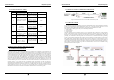
5.4 WALL MOUNT INSTALLATION
z Position the Wall Mount to the location where you install the unit and mark 4 x drilling position. Drill 6-
32 holes at least 4 mounting point.
z Drill 1/2” hole on the center of Wall Mount.
z Using 4 screws, install the Wall Mount to the proper location.
z Take out the cable through the center hole.
z After the wiring is done on the section 8, install the Main Unit to the Wall Mount using a screw to the
bottom of the Wall Mount.
6. WIRING
6.1 POWER CONNECTION
1. Connect (+) wire of DC 12V power Supply to the Red wire.
2. Connect GND (-) wire of DC 12V power Supply to the Black wire.
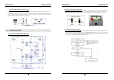
6.2 INPUT CONNECTION
Exit Button Connection
1. Connect one wire from an Exit Button to the Orange wire.
2. Connect the other wire from the Exit Button to the GND.
Door Contact Sensor Connection
1. Connect one wire from a Door Contact Sensor to the Purple wire.
2. Connect the other wire from the Door Contact Sensor to GND.
Auxiliary Input Connection
Applied to Aux Input #1(Pink wire), Aux Input #2(Cyan wire)
1. Connect one wire from an Auxiliary Input Device to one of the Aux Input #1 or Aux Input #2.
2. Connect the other wire from the Auxiliary Input Device to GND.
Figure: Input Device Connection
GE AccessSmart 313 Last Update July 6, 2005
18
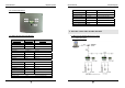
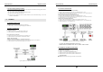
6.3 OUTPUT CONNECTION
Door Lock (Power Fail Safe) Connection (Door Relay)
1. Connect COM wire of Door Relay, the Green wire with white stripe to +12V.
2. Connect NC wire of Door Relay, the Gray wire with white stripe to (+) wire of door lock device.
3. Connect GND wire to (-) wire of door lock device.
Door Lock (Power Fail Secure) Connection (Door Relay)
1. Connect COM wire of Door Relay, the Green wire with white stripe to +12V.
2. Connect NO wire of Door Relay, the White wire with red stripe to (+) wire of door lock device.
3. Connect GND wire to (-) wire of door lock device.
Alarm Device Connection (Alarm Relay)
1. Connect COM wire of Alarm Relay, the Brown wire with white stripe to +12V.
2. Connect NO wire of Alarm Relay, the Blue wire with white stripe to (+) wire of Alarm device.
3. Connect GND port to (-) wire of Alarm device.
Figure: Door Lock, Alarm Device Connection
CAUTION: Must add REVERSE DIODE as shown above.
DIODE: Fast Recovery DIODE (current: min. 1A), 1N4004 ~ 1N4007 or similar.
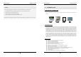
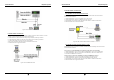
6.4 EXTERNAL READER CONNECTION
Proximity Reader Connection
1. Connect (+) wire of the Proximity Reader to DC +12V.
2. Connect (-) wire of the Proximity Reader to GND.
3. Connect Data-0 wire of the Proximity Reader to the Green wire.
4. Connect Data-1 wire of the Proximity Reader to the White wire.
z Compatible Reader:
GE616: Standard IDC 26bit Wiegand Format Proximity Reader.