
User Manual

2
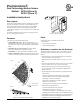
PrecisionLine RCR-A/RCR-C
Installing the Detector
All wiring must conform to National Electric Code (NEC) and/or
local codes having jurisdiction.
Important: DO NOT use this device for safety
interlock applications.
Use the following steps to install the detector:
1. Run the security system wiring to the detector location.
2. To remove the front cover/electronic module, press down on
the lever at the bottom of the unit and pull the cover off.
Remove the nameplate and loosen the screw if necessary. To
remove the nameplate, insert a small screwdriver into one of
the nameplate side slots and gently push in on the nameplate.
See Figure 2.
CAUTION
You must be free of all static electricity before
handling sensor circuit boards. Touch a grounded,
bare metal surface before touching circuit boards or
wear a grounding strap
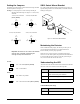
3. If necessary, set the jumpers on the circuit board. See Setting
the Jumpers.
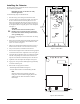
4. Remove the appropriate wiring and mounting knockout holes
from the back cover. The detector can be mounted on a flat
wall or in a corner. See Figure 3.
5. Pull the wires through the knockout holes and use screws to
attach the base to the wall. Use screw anchors if necessary.
6. Strip 1/4 inch (6.4mm) of insulation from each wire.
7. Run each wire through the strain relief and into the appropriate
screw terminals on the base. Tighten the screws. See Figure 3.
8. Line up the tabs on the bottom of the cover/electronic module
with the corresponding tabs on the bottom of the base and
snap the cover/electronic module firmly down onto the base.
9. Tighten the screw and replace the nameplate. See Figure 2.
10. Apply power. The green LED should light for approximately
25 seconds and then go out.
11. Walk test the coverage pattern as follows:
– Walk throughout the intended coverage area.
– Verify the detector alarms. See Understanding the LED.
Note
Most units walk test more accurately if the person
testing waits 10 seconds between tripping the unit and
walking again. This allows the detector to stabilize
between trips.
Figure 3. Detector Base
Terminal
sockets
Spare
RCR-C only
Flatwall-mount
knockout
Corner-mount
knockouts
Strain relief
Wiring knockout
Flat-wall mount
knockout
Wire
Corner-mount
knockouts
Figure 4. Main Circuit Board
Radar
only
J4
J3
J2
LED
Disable
Range