
User Manual

3
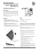
PrecisionLine RCR-A/RCR-C
Understanding the LED
The multi-color LED located on the bottom of the detector indicates
the status of the unit as described in the following table.
Maintaining the Detector
When installed and used properly, the detector provides years of
service with minimal maintenance. You should walk test the
detector annually to ensure proper operation.
When the cover is removed, power is interrupted to the sensor.
Once the cover has been replaced, the green LED will illuminate for
25 seconds while the sensor warms up. After the green LED goes
off, wait one minute and walk test the sensor.
SB01 Swivel Mount Bracket
For ceiling-mount applications that require 90 degree coverage, an
optional ceiling-mount swivel bracket (SB01) is available from GE
Interlogix. See Figure 5.
Figure 5. SBO1 Swivel-Mount Bracket
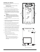
Setting the Jumpers
The detector provides jumpers to select the detection range and PIR
and LED operation. See Figure 4.
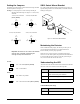
J2 Range - Use the jumper to cover the center pin and the pin
indicating the desired range. No jumper = 35 feet (10.7m)
and under.
35 feet (10.7m) and under 27 feet (8.2m)and under
(factory default)
18 feet (5.5m)and under 9 feet (2.7m) and under
In Stealth Mode (radar only):
LED Status
Red Radar detection.
Important: You need to set J2 as close to the intended
coverage range as possible. Overshooting the
coverage area may cause false alarms.
J3 LED -
ON = LED enabled (factory default)
OFF = LED disabled
J4 PIR -
ON = Radar only enabled
OFF = PIR and radar enabled (factory default)
9’
(2.7m)
18’
(5.5m)
35’
(10.7m)
27’
(8.2m)
9’
(2.7m)
18’
(5.5m)
35’
(10.7m)
27’
(8.2m)
9’
(2.7m)
18’
(5.5m)
35’
(10.7m)
27’
(8.2m)
9’
(2.7m)
18’
(5.5m)
27’
(8.2m)
35’
(10.7m)
LED Status
Red PIR and radar detection. The detector is in
alarm and the relay has switched.
Green PIR detection only (no alarm).
Yellow Radar detection only (no alarm).