
Installation Guide
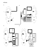

Red: Positive 9 to 14 VDC supply
Black: 0 Volts DC supply ground
Green: D0 / Clock RS485 Data - Wiegand Data 0
Absolute maximum, 12 V @ 10mA
White: D1 / Data RS485 Data + Wiegand Data 1
Absolute maximum, 12 V @ 10mA
Brown: LED 1 Offline LED control configured to “Two Wire Control” will control
the red LED only.
Wire grounded: red LED on
Wire open: red LED off
Wire at +5 V to +12 V: Red LED off or, offline LED control config-
ured to “One Wire Control” will control both the red and blue LEDs
Wire grounded: blue LED on
Wire open circuit: Both LEDs off
Wire at + 5 V to 12 V: red LED on
Absolute maximum, 14 V
Yellow: LED 2 Configurable to control the blue LED when offline
Wire grounded: blue LED on
Wire open: blue LED off
Wire at +5 V to +12 V: blue LED off
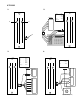
Request to exit input when online to Advisor Master
This input may be connected to a simple push button connected to
Ground with RTE Only selected on the option card or in Menu 10 (See
Programming Guide for more details).
Blue: Buzzer Offline buzzer control.
Wire open or +5 V to +12 V: buzzer off
Wire grounded: buzzer sounding
Absolute maximum, 14 V
Violet: Open Collector Configurable as: door relay, - tamper output, credit controlled
pulsed, timed or latched output
Note: This is a low current output and must not be used to directly
energize high current door openers.
Absolute maximum, 14 V @ 25mA
Current consumption 80mA max.
Input voltage 9VDC min., 14VDC max.
Operating temperature -31° F to 150° F (-35° C to 66° C)
Humidity 95% non-condensing
This device complies with Part 15 of the FCC rules. Operation is subject to the following three conditions:
1. This device may not cause harmful interference.
2. This device must accept any interference received, including interference that may cause undesired
operation.
3. Changes or modifications not expressly approved by the party responsible for compliance could void the
user’s authority to operate the equipment.
FCC ID: CGGATS1190-1192
Reader Wiring
Technical
Specifications
FCC
Complicance